COMPONENT MAINTENANCE MANUAL
IN 1502H RADAR INDICATOR
TM109102
6-1
May/01
SECTION VI ILLUSTRATED PARTS LIST
1. INTRODUCTION
The Illustrated Parts List (IPL) is a complete list of assemblies and parts required for the unit.
The IPL also provides for the proper identification of replacement parts. Individual Bills of
Material (BOM) within this IPL are arranged in numerical sequence starting with the top
assembly and continuing with the sub-assemblies. All mechanical parts will be separated
from the electrical parts used on the sub-assembly. Each BOM is followed by the Assembly
Drawing and Schematic Diagram for that assembly.
Parts identified in this IPL by Telephonics Part Number meet design specifications for this
equipment and are the recommended replacement parts. Warranty information concerning
Telephonics replacement parts is contained in Service Memo #1, P/N 600-08001-00XX.
Some part numbers may not be currently available. Consult the current Telephonics catalog
or contact a Telephonics representative for equipment availability.
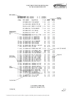
This section describes the various items that appear on the Bills of Material. A sample BOM
is included in this section as Figure 6-1.
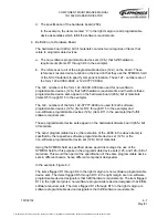
A. BOM Number
The Bill of Material Number appears at the top of the BOM as a 12-digit number which is
also the Telephonics Part Number for the assembly. The BOM Number is followed by the
assembly description and the revision level of the BOM.
B. Symbol Column
This column contains the Reference Designators of the electrical components of the
assembly. Mechanical parts are not assigned Reference Designators; however, they may
be assigned item numbers to assist in locating the part on an assembly drawing. The
Reference Designator consists of a letter abbreviation which indicates the type of
component followed by the number assigned to that part (C101, Q101, etc). Common
Reference Designator abbreviations are listed below.
B
Motor or Synchro
Q
Transistor
C
Capacitor
P
Plug
CJ
Circuit Jumper
R
Resistor
CR
Diode
RT
Thermistor
DS
Lamp
S
Switch
F
Fuse
T
Transformer
FL
Filter
TP
Test Point
I
Integrated Circuit
U
Resistor/Capacitor
Network/Integrated Circuit
J
Jack
V
Photocell/Vacuum Tube
L
Inductor
WG
Waveguide
M
Meter
Y
Crystal
The document reference is online, please check the correspondence between the online documentation and the printed version.


