COMPONENT MAINTENANCE MANUAL
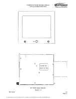
IN 1502H RADAR INDICATOR
TM109102
1-1
May/01
SECTION I THEORY OF OPERATION
1. General
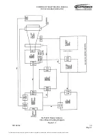
This section provides theory of operation of the IN 1502H Radar Indicator on three levels:
overall operation within the RDR-1500B Radar System, block diagram operation of the
indicator and detailed theory of operation.
2. Overall Operation
Figure 1-1 in Part 3 of the RDR-1500B System Manual (IB21500B), Volume One TM109302
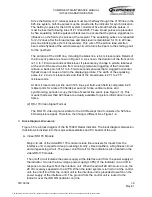
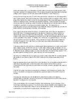
(006-15589-0000) illustrates the typical RDR-1500B Radar System. A single connector at
the rear of the indicator handles all inputs from the IU 1507A Interface Unit and from the
aircraft. The indicator provides no output signals. Refer to Table 1-1 for identification of all the
signals and voltages at the indicator connector, J3001.
Connector J3001 Inputs
Table 1-1
J3001 PIN
SIGNAL NAME AND DESCRIPTION
1 and 2
28 Vdc; from aircraft 28 Vdc power source.
3
COMP VIDEO EN; enables composite video (CCIR or RS-170) input when
grounded.
4 and 5
Ground; aircraft ground. (Pin 4 also serves as COMP VIDEO shield.
6
CCIR/RS170: when grounded, selects RS-170 composite video if pin 3 (COMP
VIDEO EN) grounded.
7
Spar e.
8
COMP VIDEO (Composite Video) HI.
9
5 Vdc; from interface unit.
10
EN DR (Enable Drive) ground interlock for interface unit.
11
Ground; from interface unit.
12
IND ON (Indicator On) from control unit.
A1 (coax)
XRET (X Retrace) from interface unit.
A2 (coax)
YRET (Y Retrace) from interface unit.
A3 (coax)
RED; red video from interface unit.
A4 (coax)
GREEN; green video from interface unit.
A5 (coax)
BLUE; blue video from interface unit.
The document reference is online, please check the correspondence between the online documentation and the printed version.

