COMPONENT MAINTENANCE MANUAL
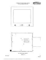
IN 1502H RADAR INDICATOR
TM109102
1-2
May/01
The indicator receives its operating power from the aircraft 28-volt dc bus. Inputs to the
indicator from the interface unit include the red, green and blue video, which are TTL inputs
used to drive the CRT color guns; and the X-retrace and Y-retrace signals, which are also
TTL signals, used to trigger the horizontal and vertical sweep circuits that develop the sweep
signals for the CRT deflection yolks. The IND ON (indicator on) input from the control unit
and +5-volt input from the interface unit are used in the indicator on/off circuit. The enable
drive connection is a ground which provides and interlock that enables the output drivers at
the interface unit. Other inputs are CCIR FLIR (forward-looking infrared) or RS-170
composite video, a composite video enable (COMP VIDEO EN) discrete input and a
CCIR/RS170 select input.
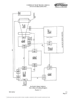
The indicator contains several circuit boards interconnected by cables. Figure 1-1 is a
simplified block diagram showing the relationship between the boards and the
interconnecting cabling.
A. Display of Interface Unit Inputs
(1) Scanning Technique
The color indicator is scanned the same way as a television screen. Scanning starts
in the upper left corner of the screen and proceeds across to the right and slightly
downward. When the right hand side is reached, the scanning spot retraces rapidly to
a position below the starting position and again proceeds to the right and slightly
downward, etc., ultimately reaching the bottom of the display. At that point, the spot
returns to the top and repeats the process, except that the lines of the second
scanning field fall between the lines of the first field. Thus, successive fields are
interlaced, permitting two fields for each frame, which greatly reduces the tendency to
flicker. (See Figure 1-2.)
The received radar video information from the antenna is in the conventional rho-theta
format. The interface unit converts this video to the X-Y format for displaying on the
indicator for displaying on the indicator CRT. The X-Y scanning technique permits
displaying other data (alphanumerics, etc.) in areas where radar video is not being
displayed and superimposing data (beacon, NAV) over the radar video. (For detailed
information on the indicator displays, refer to Part 1 of the RDR-1500B System
Manual (IB21500B), Volume One TM109302 (006-15589-0000).
All the data for the complex display is stored in memories at the interface unit and
displayed at the proper time when the memories are addressed as the CRT is
scanned.
(2) Screen Format (See Figure 1-2.)
Using interlaced scanning, two fields constitute one frame. During each field, the
screen is scanned in 256 horizontal lines, for a total of 512 different lines per frame.
On each line, 512 bits of information are displayed, for a total of 262,144 locations
(512 x 512) within the 4.5 x 3.5 inch viewing area of the CRT at which information may
be displayed.
The document reference is online, please check the correspondence between the online documentation and the printed version.

