COMPONENT MAINTENANCE MANUAL
IN 1502H RADAR INDICATOR
TM109102
1-4
May/01
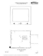
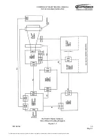
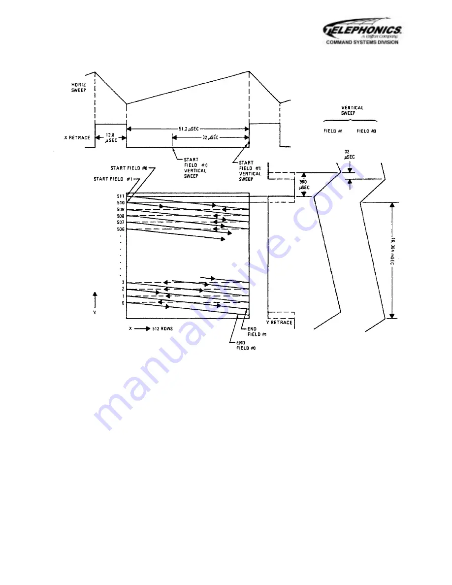
Indicator Screen
Format
Figure 1-2
Each bit on a line is located by a value of “X”. Each line of the screen is located by a
value of “Y”. Each location on the screen has a corresponding location in memory at
the interface unit. The “X” and “Y” values of the two locations on the screen can thus
be used to address the memory to write the information into the proper locations in
memory for temporary storage, and then to read out and display the information
stored there when the proper time in the scan occurs.
As the screen is scanned, the memory is addressed at each point on each line. The
data stored in the memory at each address is supplied to video amplifier circuits at the
indicator to turn on the appropriate color gun(s) in the CRT.
The red, green and blue video data from the interface unit are clocked out of memory
at 10 MHz. Thus, the horizontal scan time for each line is about 51.2 microseconds
(512 x 1/10 MHz).
The document reference is online, please check the correspondence between the online documentation and the printed version.


