COMPONENT MAINTENANCE MANUAL
IN 1502H RADAR INDICATOR
TM109102
1-10
May/01
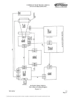
However, before the on/off circuit can switch on the interface unit power supply, it must
receive a +5 Vdc input from the interface unit power supply. Thus, when composite video
is not selected for display, the indicator can not be turned on until the interface unit is
operating.
The EN DRIVE line, which is tied to aircraft ground when the indicator is connected into
the system and composite video ENABLE is ungrounded, provides an interlock for
enabling the video, X-retrace and Y-retrace line drivers at the interface unit. Thus, if an
indicator is not connected, the interface unit line drivers do not operate. The on/off circuit
is bypassed by a grounded composite video ENABLE input and it provides the ground
necessary to switch on the power supply, regardless of whether or not the radar system is
on or even connected.
The COMP/RDR (composite/radar) select circuit is a relay circuit that switches signal
routing within the indicator to allow display of CCIR or RS-170 “TV” video. By grounding
the ENABLE line, the user selects a 625-line, 60Hz (RS-170) format for display. This
circuit then provides active-high ENABLE and active-low EN outputs to the sweep module
to set up the horizontal and vertical drive circuits to accept composite video from the
aircraft, rather than RGB (red, green, blue) video from the radar system. The EN signal is
also gated to the input circuit for interface unit video to disable these video inputs. Also,
the ENABLE signal is applied to a multiplexer (COMP/RDR RETRACE MUX) where
X-retrace and Y-retrace signals from the composite video processing circuits are selected
for use by the sweep module and those from the interface unit are deselected.
The COMP/RDR SELECT relay switches the CRT gun (green) input to the output from
the composite video processing circuits. The CCIR and RS-170 composite video inputs
are processed identically on the video/RS-170 module. Differences between the two
signals are compensated for on the sweep module in response to the RS170 input from
the aircraft. This is explained later.
When the ENABLE line is not grounded, the indicator displays radar/overlay information
as received from the interface unit. The RED, BLUE and GREEN digital data, as well as
the X-retrace (XRET) and Y-retrace (YRET) inputs, are received at TTL levels from the
interface unit. After buffering, the video data is converted to MOS levels and routed to
video amplifiers which drive the CRT guns. The buffered X-retrace and Y-retrace signals
are applied to a multiplexer (COMP/RDR RETRACE MUX) which forwards these signals
to the sweep circuits if composite video is not selected. If composite video is selected
(ENABLE line from the aircraft grounded), the interface unit retrace signals are disabled
and retrace signals (XRET and YRET) from the FLIR interface module are used instead.
The TTL-to-MOS converters transform the video signals to levels necessary for driving
the color guns at the CRT. These outputs to the CRT are digital in the sense that each of
the three colors is fully on or off. The CRT guns are turned off by +65 volts and on by
voltages near zero volts, or ground. Balancing of the three guns is accomplished by
adjusting the outputs to somewhere between -9 and +9 volts when the guns are on. A
perfect balance results in pure white on the screen when all three guns are on. This circuit
is disabled when FLIR video is being displayed (ENABLE activated). It is also disabled by
an inactive VID EN from the sweep module, which sets this signal low should the
horizontal drive output fail, thus providing phosphor protection to the CRT.
The document reference is online, please check the correspondence between the online documentation and the printed version.


