COMPONENT MAINTENANCE MANUAL
IN 1502H RADAR INDICATOR
TM109102
1-11
May/01
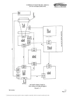
The degaussing circuit generates a decaying magnetic field around the picture tube at
2-second to 3-second intervals when the indicator is on. The circuit includes a capacitor
which is charged to a predetermined level by +250 volts from the horizontal sweep circuit
on the sweep module. Once the voltage reaches this level, the next Y-retrace pulse
discharges the capacitor through the degaussing coil to ground. Degaussing occurs only
during the retrace interval while no video is being written on the screen.
The brightness circuit receives -160 volts from the horizontal sweep circuit and is
controlled by the BRT (brightness) control on the front panel of the indicator. The output of
this circuit is applied to G1 (grid 1) of the CRT when interface unit data is being displayed.
Maximum brightness is obtained when this output is the least negative. Two adjustments
are provided in this circuit, for setting the minimum and maximum brightness levels
obtainable using the front panel BRT control. When composite video is selected
(ENABLE = 1), the output of this circuit, as controlled by the BRT control, is applied to the
composite video processing circuitry to set the level of the composite video applied to the
green gun of the CRT. If the horizontal drive output from the sweep module fails, the VID
EN input to this circuit disables the composite video output to the CRT for phosphor
protection purposes.
The composite video input from the aircraft, which arrives at a level of approximately 1
volt peak-to-peak, is first applied to a video AGC amplifier which compensates for
variation in the video signal level. The horizontal and vertical sync signals are separated
from the video by the H sync and Y sync detectors, respectively. Since the frequency
distribution of the vertical and horizontal sync signals differs widely, it is possible to
separate the vertical, horizontal and video signals by filtering, which is essentially how
these two circuits operate.
The video signal, after sync separation, is applied to a DC resistor circuit. This circuit
reinserts the DC component of the video signal to prevent the average brightness level of
the displayed video from being affected by its varying video content. The vertical blanking
signal which is coincident with YRET, is also applied to this circuit to blank lines during the
vertical retrace period.
The output from this circuit is applied to a video processor that consists of a multiplier
followed by a video amplifier, which provides the correct amount of amplification to the
video before it is routed to the CRT. The level of the output video is variable, using the
front panel BRT control, producing a picture that is blank at the minimum brightness
setting and bright at the maximum setting. The composite video section of the brightness
control circuit contains adjustments to guarantee this condition. This circuit produces an
output that varies from 0 volts (minimum brightness) to +3 volts (maximum brightness)
and this is applied to a linear multiplier in the video processor circuit to control amplitude
of the video output signal.
The line sync pulse, after sync separation, is used to trigger the horizontal blanking and
DC restoration signals. The output from the horizontal blanking circuit goes to the
horizontal position circuit on the sweep module, via the COMP/RDR RETRACE MUX.
The document reference is online, please check the correspondence between the online documentation and the printed version.


