COMPONENT MAINTENANCE MANUAL
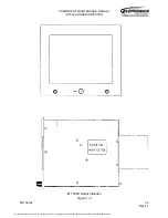
IN 1502H RADAR INDICATOR
TM109102
1-12
May/01
The Y-retrace signal (YRET) is produced by simply using the field sync output of the V
sync detector to trigger a one-shot multivibrator. The duration of this output pulse is fixed
at 1800 microseconds. This signal is also multiplexed to the sweep module where it is
used by the pincushion and vertical sweep circuits when composite video is selected.
B. Sweep Module
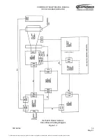
The sweep module contains the analog circuits which develop the sweep signals for the
CRT. The X-retrace (XRET) input signal is used to develop the horizontal sweep. The
Y-retrace (YRET) input signal is used to develop the vertical sweep. Circuits included on
the sweep board are the horizontal position, horizontal sweep, pin-cushion, vertical size
and position, and vertical sweep circuits. The CCIR/RS-170 select circuit produces
outputs to the horizontal and vertical drive circuits to set up their timing for the type of
video selected; radar, CCIR, or RS-170.
The horizontal sweep is produced by the horizontal sweep circuit driving the horizontal
windings of the deflection yoke, mounted at the neck of the CRT. The horizontal position
circuit permits centering of the video on the screen horizontally. The horizontal sweep is
terminated by the X-retrace signal to allow horizontal retrace.
The X-retrace signal is applied to the horizontal position circuit, which is an adjustable
analog delay circuit. This circuit provides separate adjustments for RS-170, CCIR and
radar horizontal position. These adjustments are switched in or out of the circuit,
depending upon type of video, to provide the correct delay for the X-retrace signal to shift
the scan in the horizontal direction and center the video on the screen. A delay is
necessary for the radar video because the X-retrace signal from the interface unit leads
the video outputs from the interface unit by about 1.6 microseconds. In the case of the
composite video, the delay is necessary to enable adjusting the picture fully to the left
side of the screen.
A linear horizontal sweep is obtained by linearly increasing the current in the yoke. This
linear deflection is produced by applying constant voltage across the inductive yoke until
current reaches a value sufficient to deflect the electron beam fully. At this point, the yoke
is, in effect, abruptly disconnected from the constant voltage source. The stored energy
in the yoke then is transferred to a capacitor by resonance. The energy in the capacitor
has sufficient time during the retrace interval to flow back into the yoke. The voltage
source is then, in effect, reconnected and the energy is returned to the yoke during the
initial part of the scanning period, while in the last part of the cycle, energy is supplied to
the yoke. Thus, large circulating energy is supplied for scanning, with little real power
dissipated in the process.
The output from the horizontal position circuit triggers the horizontal sweep circuit to
initiate horizontal retrace. The leading edge of the trigger turns off the horizontal output to
the yoke. The current from the yoke now charges a flyback capacitor for one-half of the
retrace period. During the second half of the retrace period, the capacitor discharges
back into the horizontal yoke, reversing the current path through the yoke. Current builds
up in the yoke until the yoke voltage reaches a preset level. At this point, the sweep circuit
locks yoke voltage at that level and initiates the horizontal sweep.
The document reference is online, please check the correspondence between the online documentation and the printed version.


