COMPONENT MAINTENANCE MANUAL
IN 1502H RADAR INDICATOR
TM109102
1-25
May/01
component of the video signal by clamping the video component to maintain the
black level during these periods. The video signal is grounded during the back
porch to set the black level via U1012B.
The vertical sync signal is a series of pulses approximately 2.5 (CCIR) or 3
(RS-170) horizontal lines in duration and occurring at the field repetition rate. It is
preceded by a series of equalizing pulses at black level to ensure that the picture
signal has no influence on the field sync pulse at the receiver. The line sync
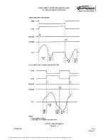
pulses and the narrow equalizing pulses (Figure 1-3 or 1-4) that occur just prior to
field sync are filtered out from the vertical sync output of U1005. But the field sync
broad pulses are wide enough to pass and switch the pin 3 output of U1005 low.
The vertical sync output at pin 3 of U1005, when it goes low, triggers a second
one-shot multivibrator, U1006A, which generates a 950-microsecond negative
going pulse output at pin 7. This is the composite video Y-retrace (YRET) pulse,
which is multiplexed with the radar YRET in U1003 and sent to the sweep module
to initiate the vertical retrace. This signal also is AND'ed with the horizontal sync
output from U1006B and applied to the DC restorer circuits. The one-shot is held
in the reset state by a logic low at pin 3 when the ENABLE line is low.
Between horizontal and vertical blanking periods (XRET and YRET), FET Q1002
is held off by a logic low level on its gate. This logic low also keeps analog switch
U1012C closed, allowing passage of video to multiplier U1011. During XRET and
YRET, however, this FET is switched on by the negative pulses from U1006B and
U1006A, respectively, inverted by U1016B. This opens the video path to U1011 by
opening U1012C and grounds the video input to U1011 via Q1002 to hold the
video line at ground (black) level during sync periods. This cuts off the CRT beam
during horizontal and vertical retrace periods.
(e) Horizontal Processor
The negative output pulses from one-shot U1006B are coupled through C1083 to
the sync input of TV horizontal processor U1021. This device contains oscillator,
phase detector and predriver sections that combine to provide a horizontal
automatic phase control loop in a single integrated circuit. The oscillator is an RC
type with R1092/RI095 and C1041, connected to pin 7, controlling the timing. The
square waveform at pin 4, derived from the X-retrace pulse, is compared with the
sync input at pin 3 to determine the phase relationship between the two signals.
When a phase offset occurs, current will flow either into our out of pin 5. If there is
no phase difference between the sync and the sawtooth (balanced condition),
there is no net output current at pin 5.
This pin is connected via an external low-pass filter (CID94, C1095, and R1096) to
pin 7, thus controlling the oscillator. During indicator alignment, potentiometer
R1092 is adjusted for an approximately 4-volt level at pin 5 (TP1020).
The duty cycle of the positive pulse at the predriver output (pin 1) is fixed by the
bias voltage on pin 8. Components R1137 and C1097 are used for ripple
rejection. The U1021 output generates the X-retrace signal for the composite
video in the RS-170/CCIR horizontal position circuit, from which it is applied to
multiplexer U1003.
The document reference is online, please check the correspondence between the online documentation and the printed version.


