COMPONENT MAINTENANCE MANUAL
IN 1502H RADAR INDICATOR
TM109102
1-27
May/01
is high. Meanwhile, the negative input to U2007A is pulled up to +5 volts via R2036.
Since its positive input is biased at +2.25 volts, the U2007B output is low between
XRET pulses. Therefore, Q2013 is turned off and MOSFET Q2010 is kept off by the
-5 volts on its gate.
The XRET pulse is inverted high by gate U2006A, U2006B, or U2006C, depending
upon whether radar, RS-170, or CCIR is selected. If radar is selected, the pin 2 input
of U2006A (ENABLE) is low to enable the NOR gate. If RS-170 is selected, the pin 5
input to U2006B is low. If CCIR is selected, the pin 8 input to U2006C is low. The
resulting positive pulse is applied through the corresponding horizontal position
potentiometer (R2040, R2041 or R2042), in parallel with R2081, to the negative input
of U2007B. This provides a path to charge C2018. The time required for C2018 to
charge above +2.4 volts (bias at U2007B) is the delay provided by the circuit. This
delay is adjustable using potentiometers R2040 (RS170 HORZ POS), R2041 (CCIR
HORZ POS), and R2042 (RDR HOR POS) for each type of video that can be selected
for display.
As soon as the charge on C2018 exceeds the 2.4-volt threshold, the output of
U2007B switches low to initiate the horizontal retrace. At the completion of XRET, the
output (pin 13) of gate U2006D switches low to discharge C2018 via R2039 and
CR2026 and the output of U2007B returns high.
(2) Horizontal Sweep Circuit
The horizontal sweep circuit produces a linear current ramp in the horizontal yoke to
deflect the CRT beam horizontally, from left to right, across the face of the CRT.
Maximum current is required in the yoke to move the beam to the left edge of the
screen at the start of a sweep. The current must then linearly decrease to zero and
increase to a maximum in the reverse direction to sweep the CRT beam horizontally.
At this time, the X-retrace (XRET) signal switches off the beam. While the beam is off,
the yoke current must rapidly be reversed from a maximum in one direction to a
maximum in the other direction in preparation for the next scan line.
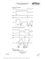
For the discussion which follows, the starting point is just prior to X-retrace, when
current is increasing linearly toward maximum to deflect the CRT beam to the right
edge of the screen. MOSFETs Q2006 and Q2007 are fully on, placing the +65 volts
from the Q2005 collector across Q2005 and L2001. The actual voltage available at
the Q2005 emitter depends upon the settings of horizontal size controls R2034 and
R2038 (discussed later). Yoke current is produced by the discharging of C2022
through Q2006/Q2007 during the last half of the horizontal sweep period.
At X-retrace time, transistor Q2010 is switched on to place ground level on the gates
of Q2006 and Q2007, shutting then off. The X-retrace pulse also triggers (resets)
timer U2008, which provides additional delay necessary for correct horizontal
positioning of the sweep, set by potentiometers in the horizontal position circuit as
described in the previous paragraph.
The energy stored in the yoke is now transferred by resonance, resulting in a large
voltage (approximately 650 volts) across R2006 and Q2007. As the voltage swings
rapidly back to zero, the current in the yoke reverses, deflecting the beam to the left
The document reference is online, please check the correspondence between the online documentation and the printed version.

