COMPONENT MAINTENANCE MANUAL
IN 1502H RADAR INDICATOR
TM109102
1-28
May/01
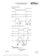
edge of the screen. The beginning of the sweep is not related to the trailing edge of
the delayed X-retrace signal, but rather to the time required for the resonant circuit to
go through one-half cycle of oscillation.
At the conclusion of the delayed X-retrace pulse, Q2010 is switched off, and Q2006
and Q2007 switch on to provide a path for the reverse current through the yoke during
the second half of the sweep. The charge stored in C2022 during the first half of the
sweep is now returned to the yoke as Q2006 and Q2007 discharge C2022 through
the yoke. Yoke current increases linearly until the next retrace signal, and the cycle
repeats.
(3) Horizontal Drive Circuit
The energy for the horizontal sweep circuit is supplied by +65 volts (-0501) or +53
volts (-0503) through Q2005 and L2001. Operational amplifier U2009A forms a
conventional voltage regulator circuit. The voltage at the output (TP2006) controls
display width and is adjustable with horizontal size potentiometers R2034 and R2038.
When CCIR or RS-170 composite video is selected for display, the EN line is set low
and this closes analog switch U2003D, allowing R2038 to increase the horizontal size.
In radar mode U2003D is open, and R2038 is disabled. The output voltage at TP2006
is modulated with the pincushion correction signal. The amount of pincushion
correction is adjustable with pincushion amplitude potentiometer R2025.
(4) Pincushion-Correction Circuit
Pincushion distortion, in which the four sides of the raster are curved inward with the
corners extended outward, results from the non-linear curvature of the CRT inside
faceplate. The result is that the electron path to the top and bottom edges of the
display is longer than that at the center. If a constant deflection angle is maintained,
the distorted image results. This pincushion distortion is corrected by slightly
increasing the deflection angle, or horizontal width, at the center portion of the vertical
scan. This is done by modulating the horizontal sweep amplitude as a function of
beam vertical position.
This correction voltage is developed by the double integrator circuit formed by
U2004A and associated components. Operational amplifier U2004A is configured as
a ramp generator. It is triggered by the YRET (Y retrace) input, which closes analog
switch U2003B at intervals of about 16.4 milliseconds. When YRET goes high
(inactive) the analog switch opens and U2004A generates a negative-going ramp.
This ramp is integrated to obtain a parabolic voltage output that is high at each end
and low in the center. The integrator is reset by the next YRET pulse. The pincushion
correction parabola is superimposed on the output of the horizontal drive circuit.
When the parabolic output voltage of U2004A is inverted by U2009A and added to the
horizontal deflection yoke current, the deflection angle becomes greater at the center
of the display than at the top and bottom. The precise amount of correction is adjusted
by pincushion amplitude potentiometer R2025. This adjustment straightens the sides.
An additional adjustment, R2020 (pincushion tilt), is adjusted to eliminate any curve at
the corners of the display.
The document reference is online, please check the correspondence between the online documentation and the printed version.


