COMPONENT MAINTENANCE MANUAL
IN 1502H RADAR INDICATOR
TM109102
1-33
May/01
The on/off circuit keeps the low voltage power supply deenergized as long as the
radar system is turned off. When the radar system is turned on, this circuit also
provides undervoltage shutdown of the LVPS in the event that the aircraft DC supply
voltage (28 volts) becomes too low.
When the radar system is turned off and the aircraft 28 volt DC source is on, the 28
volts is applied to the LVPS via pins 29 through 34 of connector J5011. This voltage is
well filtered and applied to 12 volt regulator U5001. Surge suppressor diode CR5012
protects U5001 against the effects of voltage transients on the 28 volt line. Resistor
R5004 provides current limiting to protect the diode.
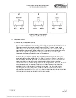
Figure 1-6 is a simplified schematic of the on/off circuit. The fi28 volts is
applied to, in addition to U5001, the collector of NPN switching transistor Q5007, via
R5005. The +12 volt output of U5001 is used only within the LVPS. It provides the
supply voltage for operational amplifier U5002, precision voltage regulator U5006 and
VCO U5003 (not shown in Figure 1-5). Through limiting resistor R5034, the +12 volts
is also used as a pullup, which is applied to the on/off line (pin 26 of J5011) and to the
base of switching transistor Q5008.
As long as the radar system is switched off at the control unit, the positive voltage
applied to the base of Q5007, via CR5013, keeps Q5007 switched on. The collector of
Q5007 is thus grounded and the negative input of U5002A is near zero volts. The
positive input of U5002A is biased at a precise 1.25 volts by dividing the 2.5 volt
output of U5006 down through precision resistors R5012 and 5020. This keeps the
output of U5002A positive and Q5008 remains cut off.
When the radar system is switched on at the remote control unit, the on/off line
becomes grounded. (Before the on/off line to the LVPS becomes grounded, the
interface unit power supply must come on and energize the on/off circuit at the
video/RS-170 module, or the composite video ENABLE line must be grounded, as
already explained.) This switches Q5007 off. The fi28 volts is now divided
down by R5005 and R5007, to a level greater than the 1.25 volt bias on pin 3 of
U5002A. This switches the output (pin 3) of U5002A low, switching Q5008 on. When
Q5008 conducts, it provides a path for +12 volts to the centertaps of proportional drive
transformers T5001 and T5002 in the driver circuit. (See Figure 6-16.) This energizes
the LVPS.
The second function of this circuit is to shut down the LVPS if the voltage level of the
aircraft DC source becomes too low. At the nominal 28 volt level, the voltage divided
down by R5005 and R5007 and applied to pin 2 of U5002A is 1.86 volts. The other
input of U5002A is biased at precisely 1.25 volts from U5006, divided down by R5012
and R5020. If the DC input from the aircraft source decreases, the voltage at the
junction of R5005 and R5007 decreases proportionately. At approximately 19 volts,
the bias on pin 2 of U5002A becomes less than the 1.25 volts at pin 3 and the output
of U5002A is switched high. This switches off Q5008, disabling the LVPS.
The document reference is online, please check the correspondence between the online documentation and the printed version.


