COMPONENT MAINTENANCE MANUAL
IN 1502H RADAR INDICATOR
TM109102
3-7
May/01
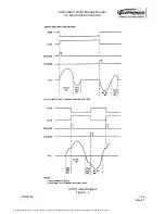
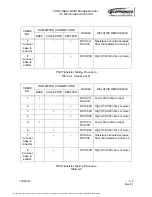
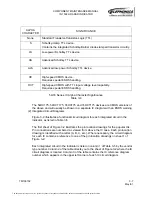
54/74 Series IC Alpha Character Significance
Table 3-4
The 54HC175, 54HCT175, 74HC175 and 74HCT175 devices are CMOS versions of
the above and will usually be shown in a separate IC diagram with an ESDS warning.
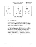
(2) Integrated Circuit Diagrams
Figure 3-2 illustrates a functional circuit diagram for each integrated circuit in the
indicator, as listed in Table 3-5.
The first sheet of Figure 3-2 illustrates the pin location drawings for the popular ICs.
Pin connections are numbered as viewed from above the IC case. Each pin location
drawing is identified with a letter (A, B, C, etc.). Where necessary, the circuit diagram
for each IC contains a reference to one of the pin location drawings on sheet 1 of
Figure 3-2.
Each integrated circuit in the indicator is listed in column 1 of Table 3-5 by the vendor
type number. Column 2 of the table directs you to the sheet of Figure 3-2 where the IC
circuit diagram is located. Column 3 of the table contains the IC reference diagram
number which appears in the upper left corner of each IC circuit diagram.
ALPHA
CHARACTER
SIGNIFICANCE
None
Standard Transistor-Transistor-Logic (TTL)
S
Schottky-clamp TTL device.
Contains the integrated Schottky-Barrier diode-clamped transistor circuitry.
LS
Low-power Schottky TTL device.
AS
Advanced Schottky TTL device.
ALS
Advanced low-power Schottky TTL device.
HC
High-speed CMOS device.
Requires special ESDS handling.
HCT
High-speed CMOS with TTL input voltage level capability.
Requires special ESDS handling.
The document reference is online, please check the correspondence between the online documentation and the printed version.


