COMPONENT MAINTENANCE MANUAL
IN 1502H RADAR INDICATOR
TM109102
4-4
May/01
3. For CCIR tests, connect the 75
Ω
coaxial cable from the COMPOSITE VIDEO
OUTPUT connector of the PAL Pattern Generator to the FLIR VIDEO connector
on the Indicator Test Panel, 8050362.
B. HI-Z FLIR Test Setup
NOTE
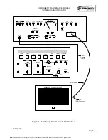
Figures 3 and 4 show the test setups required to align the
066-01170-0300 and 066-01170-0400 HI-Z FLIR versions of the
IN-1502H Radar Indicator. The LCG-396 is used to perform the
RS-170 portions of the alignment (Figure 3), while the LCG-399A is
used to perform the CCIR portions of the alignment (Figure 4).
1. Connect the UUT Test Cable, 3614370-0000, from the UUT connector on the Indi-
cator Test Panel to the P1 connector (rear connector) on the IN-1502H UUT.
2. Connect the 82
Ω
Feed-Thru Terminator to the FLIR VIDEO connector on the
Indicator Test Panel, 8050362, using the female-female BNC coupler.
3. For the RS-170 tests, connect the 75 ohm coaxial cable from the VIDEO OUTPUT
connector of the NTSC Pattern Generator to the open end of the 82
Ω
Feed-Thru
Terminator.
4. For the CCIR tests, connect the 75
Ω
coaxial cable from the COMPOSITE VIDEO
OUTPUT connector of the PAL Pattern Generator to the open end of the 82
Ω
Feed-Thru Terminator.
The document reference is online, please check the correspondence between the online documentation and the printed version.

