COMPONENT MAINTENANCE MANUAL
IN 1502H RADAR INDICATOR
TM109102
4-9
May/01
5. ALIGNMENT PROCEDURE
A. Power Input
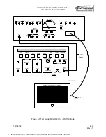
1. Connect the DMM to the Power Output banana jacks (just above POWER) on the test
panel (Red +, Black -).
2. Set the test panel POWER switch to the ON position.
3. Set the UUT power switch on the test panel to the ON position while observing the
front-panel meter on the test panel.
NOTE:
A slight leftward kick of the panel meter is normal when the switch is first turned
to the ON position, but the meter should quickly return to approximately center
scale. A high current condition in the UUT is indicated if the meter drops low
and does not return to center scale. If this occurs, quickly return the UUT power
switch to the off position to avoid blowing the test panel fuse. Troubleshoot and
correct the cause of the high current drain before restoring power to the unit.
4. Verify that the DMM reads 28.0 ± 1.0 VDC.
5. Set the UUT power switch on the test panel to the OFF position. Remove the DMM.
B. Low Voltage Power Supply Alignment
NOTE:
Refer to the Low Voltage Power Supply Module drawing for component
locations.
1. If required, remove the Low Voltage Power Supply Cover.
2. Connect the DMM to right side of R40 (positive lead) and chassis ground (negative
lead). Set the DMM for DCV.
3. Preset the 5V Adjust control, R31 on the Low-Voltage Power Supply Module, to the
full CCW position.
4. Set the UUT power switch on the test panel to the ON position.
5. Adjust the 5V Adjust control, R31 on the Low-Voltage Power Supply Module, for a volt-
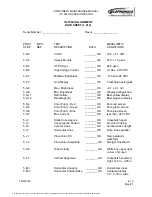
age of +5.0 + 0.1 VDC. Check the data sheet.
6. Return the UUT power switch on the test panel to the OFF position. Remove the
DMM leads.
The document reference is online, please check the correspondence between the online documentation and the printed version.


