COMPONENT MAINTENANCE MANUAL
IN 1502H RADAR INDICATOR
TM109102
4-12
May/01
G. Color Gun Settings and Brightness Control
1. Set the GREEN SCREEN switch to the up position.
2. Rotate the BRT control fully CW.
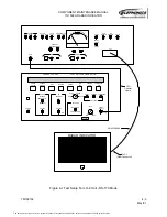
3. Connect the negative lead of the DMM to TP12 and the positive lead to TP14 on the
Video Module. Set DMM to the 200mV range.
4. Adjust the Maximum Brightness control, R83 on the Video Module, to obtain a reading
of +3.1 ± 0.1 mV on the DMM. This indicates a cathode current of approximately
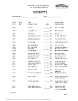
400µA at a 77% duty cycle. Check the data sheet.
5. Remove the DMM leads.
6. Return the GREEN SCREEN switch to the down position.
7. Set the COLOR BAR switch to the up position.
8. Rotate the BRT control fully CCW.
9. Adjust the Minimum Brightness control, R86 on the Video Module, until the display
just extinguishes. Check the data sheet.
10. Advance the BRT control CW until a low-intensity color-bar pattern is visible on the
screen.
11. Adjust the Red Adjust control, R47 on the Video Module, to obtain the best yellow
color on the color-bar pattern. Check the data sheet.
12. Adjust the Blue Adjust control, R57 on the Video Module, to obtain a good magenta
color. Check the data sheet.
13. Rotate the BRT control CCW and observe that all colors cut off at the same time.
14. If necessary, adjust the color controls R47 and R57 to obtain the required color bal-
ance and cutoff conditions.
15. Return the COLOR BAR switch to the down position.
H. Color Purity
NOTE:
The purity magnets on the CRT deflection yoke are pre-aligned from the vendor
and should not need realignment. If necessary, however, the purity magnets
(the two front most rings on the rear of the deflection yoke) may be rotated to
correct the display purity. After any changes are made to the purity magnet
positions, they must be secured in place with 016-01024-0000 Corona Dope.
NOTE: The 066-01170-0200 and the 066-10070-0400 units are equipped with a CRT
filter that is designed to operate with NVG. The NVG filter will not transmit the
color red correctly, and red will appear orange through this filter. Due to this
distortion of the red color, white may appear slightly blue through the NVG filter.
1. Connect the DMM to the Current Measurement banana jacks on the test panel. Set
the DMM for V DC.
2. Rotate the Brightness Knob to the Max Brightness position. Set the RED SCREEN
switch to the up position. Verify that the display is red, with no blue or green present.
Check the data sheet.
3. Return the RED SCREEN switch to the down position.
The document reference is online, please check the correspondence between the online documentation and the printed version.


