COMPONENT MAINTENANCE MANUAL
IN 1502H RADAR INDICATOR
TM109102
4-13
May/01
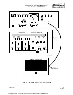
4. Set the GREEN SCREEN switch to the up position. Verify that the display is green,
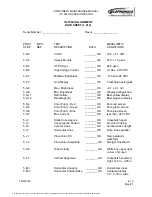
with no blue or red present. Check the data sheet.
5. Return the GREEN SCREEN switch to the down position.
6. Set the BLUE SCREEN switch to the up position. Verify that the display is blue, with
no red or green present. Check the data sheet.
7. Set the RED, GREEN, and BLUE switches to the up position and the Brightness Con-
trol to max brightness. Verify that the screen display is white and that the voltage dis-
played on the DMM is less than .350 VDC (corresponds to 3.5 A DC). Check the data
sheet.
8. Return the RED, GREEN, and BLUE switches to the down position.
I. Static Convergence Adjustment
NOTE:
The convergence magnets on the CRT deflection yoke are pre-aligned from the
vendor and should not need realignment. If necessary, however, the
convergence magnets (the four rear most rings on the back of the deflection
yoke) may be rotated to improve the display convergence. After any changes
are made to the convergence magnet positions, they must be secured in place
with 016-01024-0000 Corona Dope.
1. Rotate the UUT BRT control fully CCW.
2. Set the FINE CROSSHATCH switch on the test panel to the up position.
3. Advance the BRT control clockwise until the crosshatch grid becomes visible on the
screen.
4. Using a plastic alignment tool, adjust the RCV control, R90 on the CRT Connector
Module, for the best overall crosshatch display. Check the data sheet.
5. Verify that the Crosshatch pattern is free of noticeable color fringing at a normal view-
ing distance of approximately 30 inches. Color fringing will appear as red, green, or
blue, shadows around the Crosshatch lines. Check the data sheet.
6. Verify that the vertical lines of the Crosshatch pattern are evenly spaced across the
screen. Check the data sheet.
7. Verify that the horizontal lines of the Crosshatch pattern appear parallel to the bezel at
a viewing distance of approximately 30 inches. Check the data sheet.
J. Pincushion Correction
1. Adjust the Pincushion Tilt control, R20 on the Sweep Module, for the proper waveform
at TP3. The waveform should exhibit negative-going parabolic excursions, with no
evidence of spiking or distortion in the parabolic region. Check the data sheet.
2. Install the Dust Cover Test Aid onto the UUT.
3. Adjust Pincushion Amplitude control, R25 on the Sweep Module, until the sides of the
crosshatch pattern are as straight as possible. Check the data sheet.
4. Return the CROSSHATCH FINE switch to the down position.
5. Return the UUT power switch on the test panel to the OFF position.
The document reference is online, please check the correspondence between the online documentation and the printed version.


