COMPONENT MAINTENANCE MANUAL
IN 1502H RADAR INDICATOR
TM109102
4-14
May/01
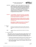
K. Verification of Yoke Polarity
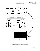
1. Orient the UUT such that the BRT control is at the bottom.
2. Set the UUT power switch on the test panel to the ON position.
3. Set the YOKE PLRT switch on the test panel to the up position.
4. Observe that a white box is present in the upper right corner of the screen. The
appearance of the white box in any corner other than the upper right corner indicates
either a deflection yoke mis-wire or a rotated deflection yoke. Correct this before pro-
ceeding. Check the data sheet.
5. Return the YOKE PLRT switch to the down position.
L. RADAR Mode Vertical Alignment
1. Install the Display Size Overlay Test Aid over the CRT.
2. Set the CROSSHATCH FINE switch to the up position.
3. Adjust R17, the RADAR Vertical Position control on the Sweep Module, until the cross-
hatch pattern is within the top boundary of the Test Aid Overlay.
4. Adjust R6, the RADAR Vertical Size control on the Sweep Module, until the crosshatch
pattern is within the bottom boundary of the Test Aid Overlay (vertical height of 5.30 ±
0.25 inches).
5. Repeat the previous two steps as necessary to obtain a crosshatch pattern of the cor-
rect vertical height and centering. Check the data sheet.
M. RADAR Mode Horizontal Alignment
1. Adjust the Horizontal Linearity control, L2 on the Sweep Module, for a crosshatch with
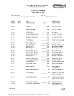
best overall horizontal linearity. Check the data sheet.
2. Adjust the RADAR Horizontal Position control, R42 on the Sweep Module, until the
display is centered on the screen
3. Adjust the RADAR Horizontal Size control, R34 on the Sweep Module, for a cross-
hatch display that is within the side boundaries of the Test Aid Overlay (7.00 ± 0.35
inches wide).
4. Repeat the previous two steps until the displayed crosshatch pattern exhibits proper
width and centering. Check the data sheet.
5. Return the CROSSHATCH FINE switch to the down position.
6. Remove the Display Size Overlay Test Aid from the CRT.
N. Focus
1. Rotate the UUT BRT control to the full CW position.
2. Adjust the Focus control, R2 on the High-Voltage Power Supply Module, for optimum
focus. Check the data sheet.
3. Return the CROSSHATCH FINE switch to the down position.
4. Return the UUT power switch on the test panel to the OFF position.
O. VCO Adjustment, Video / RS-170 Module
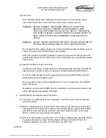
1. Remove the Dust Cover Test Aid from the UUT.
The document reference is online, please check the correspondence between the online documentation and the printed version.


