COMPONENT MAINTENANCE MANUAL
IN 1502H RADAR INDICATOR
TM109102
4-15
May/01
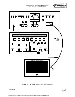
2. Connect the COMPOSITE VIDEO OUTPUT of the LCG-399A PAL Pattern Generator
to the FLIR VIDEO input of the test panel, with a 75
Ω
coaxial cable.
3. Set the VIDEO OUTPUT control to the PRESET position.
4. Select the Luminance-Bars pattern on the LCG-399A PAL Pattern Generator.
5. Set the FLIR ENABLE switch to the up position.
6. Set the RS170 / PAL switch to the PAL position.
7. Switch the UUT power switch on the test panel to the ON position.
8. Adjust the VCO Adjust control, R92 on the Video / RS-170 Module, for +4.0 ± 0.05
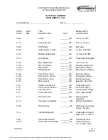
VDC at TP20. Check the data sheet.
P. Composite-Video BRT Control Alignment
1. Set the UUT BRT control fully CCW.
2. Adjust the Brightness Gain control, R94 on the Video / RS-170 Module, for a voltage of
0 ± 0.01 VDC at TP18. Check the data sheet.
3. Set the UUT BRT control fully CW.
4. Adjust the Brightness Cal control, R93 on the Video / RS-170 Module, for a voltage of
+3.0 ± 0.02 VDC at TP18. Check the data sheet.
5. Repeat the previous four steps until the voltage at TP18 varies from 0 ± 0.01 VDC to
+3.0 ± 0.02 VDC as the unit BRT control is rotated from the fully CCW position to the
fully CW position. Check the data sheet.
6. Return the UUT power switch to the OFF position.
Q. FLIR Gain Adjustment
1. Connect the VIDEO OUTPUT of the LCG-396 NTSC Pattern Generator to the FLIR
VIDEO input of the test panel, with a 75
Ω
coaxial cable.
2. Connect a 50
Ω
coaxial cable from the SCOPE TRIGGER OUTPUT of the LCG-396
Pattern Generator to the external trigger input of the oscilloscope.
3. Set the VIDEO OUTPUT LEVEL control of the LCG-396 NTSC Pattern Generator to
the PRESET position.
4. Select the Luminance-Bars pattern on the LCG-396 NTSC Pattern Generator by
depressing the COLOR, IQW OFF, and CHROMA-OFF buttons.
5. Set the SCOPE TRIGGER switch on the LCG-396 NTSC Pattern Generator to the
horizontal position.
6. Set the RS170 / PAL switch to the RS170 position.
7. Condition the oscilloscope to trigger from an external source on the rising edge of the
trigger signal.
8. Set the UUT power switch on the test panel to the ON position
9. Rotate the UUT BRT control fully CCW.
10. Adjust the Bias Control adjustment, R50 on the Video / RS-170 Module, until the hori-
zontal retrace lines are not visible on the CRT. Check the data sheet.
11. Rotate the UUT BRT control fully CW.
12. Adjust the Gain Control adjustment, R52 on the Video / RS-170 Module, until the most
negative portion of the waveform at TP17 is at +6.0 ± 1.0VDC. Check the data sheet.
The document reference is online, please check the correspondence between the online documentation and the printed version.


