COMPONENT MAINTENANCE MANUAL
IN 1502H RADAR INDICATOR
TM109102
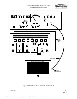
4-17
May/01
3. Set the VIDEO OUTPUT LEVEL control of the LCG-396 NTSC Pattern Generator to
the preset position.
4. Switch the RS170 / PAL switch to the RS170 position.
5. Switch the UUT power switch on the test panel to the ON position.
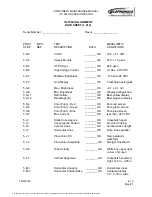
6. Adjust the RS-170 Vertical Position control, R22 on the Sweep Module, for a dis-
played pattern with very slight overscan at the top of the screen. Check the data
sheet.
7. Adjust the RS-170 Vertical Size control, R5 on the Sweep Module, for a displayed pat-
tern with very slight overscan at the bottom of the screen. Check the data sheet.
8. Repeat the previous two steps until a properly centered crosshatch display (center dot
of crosshatch display in the center box of the Display Overlay) of the correct height is
obtained.
U. RS-170 Mode Horizontal Alignment
1. Adjust the RS-170 Horizontal Position control, R40 on the Sweep Module, for a dis-
played pattern that is horizontally centered (center dot of crosshatch display in the
center box of the Display Overlay). Check the data sheet.
2. If required, readjust R38 to obtain a full horizontal overscan.
V. Power Down
1. Place the UUT power switch to the OFF position.
2. Set the test panel POWER switch to the OFF position.
3. Disconnect the UUT from the test set observing ESD precautions.
4. Remove the Dust Cover Test Aid.
5. If this procedure was performed for the Post Burn-In/Thermal Cycle Alignment, rein-
stall the Low Voltage Power Supply cover and the Sweep Module cover.
The document reference is online, please check the correspondence between the online documentation and the printed version.

