COMPONENT MAINTENANCE MANUAL
IN 1502H RADAR INDICATOR
TM109102
4-18
May/01
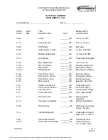
IN-1502H ALIGNMENT
DATA SHEET (1 of 2)
Serial Number: ___________________
Flavor_________________
PROC
MPS
TEST
MEASLIMITS/
STEP
REF
DESCRIPTION
DATA
CONDITIONS
5.B.5
5 VDC
________ OK
+5.0 ± 0.1 VDC
5.C.8
Sweep Module
________ OK
67.0 ± 1.0 µsec
5.D.3
HVPS Sync
________ OK
64.5 µsec
5.D.6
High Voltage Control
________ OK
+3.92 ± 0.15 VDC
5.E.7
Min/Max Brightness
________ OK
-140 and -85 VDC
5.F.3
Grid Display
________ OK
Crosshatch extinguish
5.G.4
Max. Brightness
________ OK
+3.1 ± 0.1 mV
5.G.9
Min. Brightness
________ OK
Display extinguished
5.G.11
Red/Yellow
________ OK
Best yellow display
5.G.12
Blue/Magenta
________ OK
Best magenta display
5.H.2
Color Purity - Red
________ OK
Pure red screen
5.H.4
Color Purity - Green
________ OK
Pure green screen
5.H.6
Color Purity - Blue
________ OK
Pure blue screen
5.H.7
Max Current
________ OK
less than .350 VDC
5.I.4
Static Convergence
________ OK
Crosshatch good
5.I.5
Convergence Pattern
________ OK
No color fringing
5.I.6
Vertical Lines
________ OK
Vertical lines straight
5.I.7
Horizontal Lines
________ OK
Horz. Lines parallel
5.J.1
Pincushion Tilt
________ OK
Neg. parabolic
waveform
5.J.2
Pincushion Amplitude
________ OK
Straight crosshatch
5.K.4
Yoke Polarity
________ OK
White box upper right
corner of screen
5.L.5
Vertical Alignment
________ OK
Crosshatch centered
Hght. of 5.3 + 0.25 in.
5.M.1
Horizontal Linearity
________ OK
Horizontal Linear
5.M.4
Horizontal Position/Size
________ OK
Centered display
7.0 + 0.35 in. wide
The document reference is online, please check the correspondence between the online documentation and the printed version.


