Telephonics Corporation
R
A D A R
S
Y S T E M S
D
I V I S I O N
TM113806 (3/10)
1-3
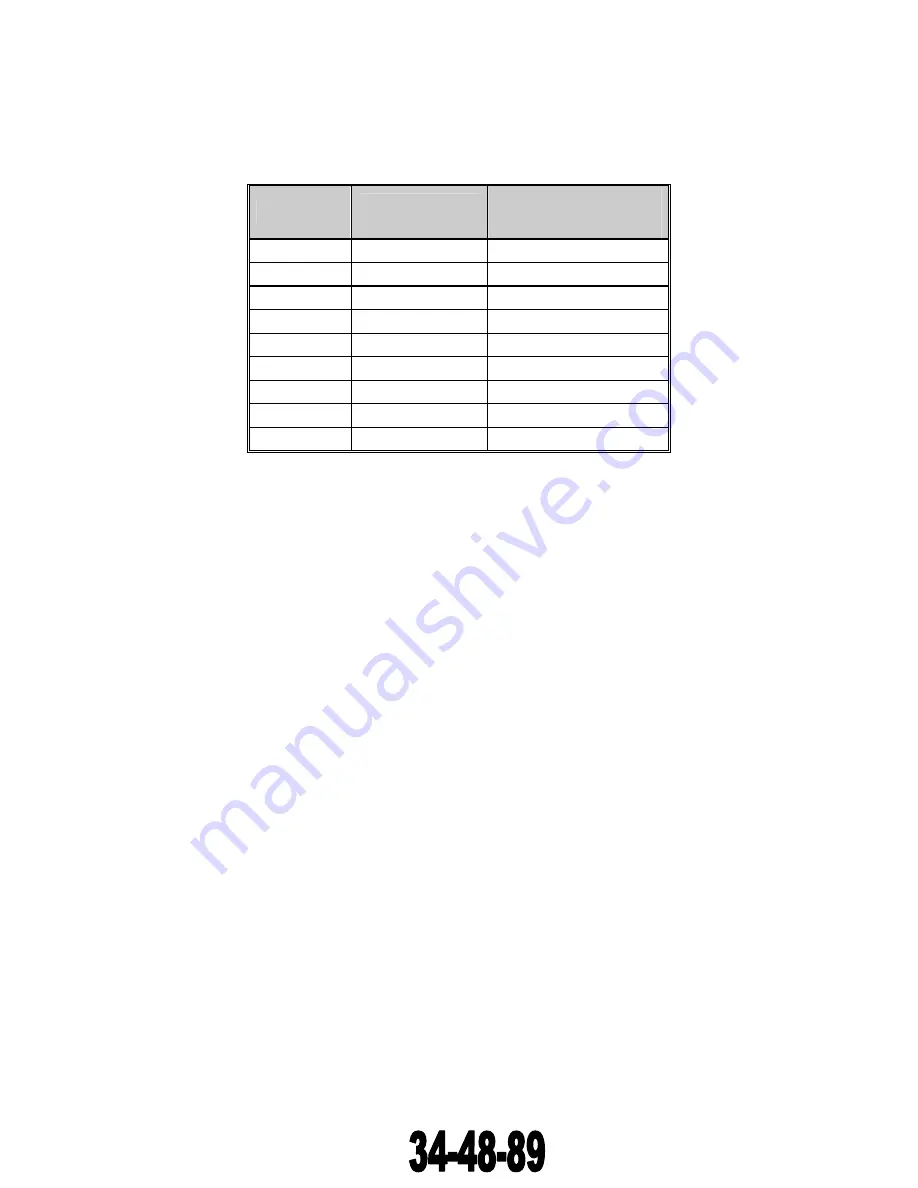
Nine range scales are selectable by the operator, each with either four or five equidistant range rings.
They are as follows:
RANGE (NM)
RANGE RINGS
(NM)
AUTO SEARCH
SELECTION
PULSEWIDTH (US)
0.625 0.125
0.1
1.25 0.25
0.1
2.5 0.5
0.1
5.0 1.0
0.1
10.0 2.0
0.5
20.0 5.0
0.5
40.0 10.0
2.35
80.0 20.0
2.35
160.0 40.0
2.35
The ability to select any pulse width for any range allows the radar operator to optimize the desired
presentation depending upon the radar operating conditions. An additional feature is the use of a (fast
time constant) control to reduce undesired clutter to enhance target detection and tracking. This control
can be used in either sea search or terrain mapping operations. The radar system has both variable STC
(sensitivity time control) and variable RF gain controls active in the search mode. The antenna rate is
selectable for either 45 deg/sec or 90 deg/sec scan rate when using the DA-1503B 360-degree Antenna
Drive Unit.
The various combinations of pulse widths, range scales, antenna rates, and other controls allow the
RDR-1700A Radar System to be used for searching for boats at sea, terrain mapping of topographical
features (bodies of water, islands, bridges, cities, etc.), and mapping of oil slicks, schools of fish at sea,
etc.
The 0.1 ms pulse can be selected on any range, but because of PRF timing, the presentation does not
extend beyond 40 NM. Again, the 0.5 ms pulse can be selected on any range scale, but because of PRF
timing, the presentation does not extend beyond 80 NM. This is not a system limitation, however, since
higher PRFs provide greater average energy on target for their intended range.
The 2.35 ms pulse can be selected on the shortest-range scales; however, the minimum detection range
for targets will increase to 2000 feet.
The radar also has an auto-search mode where the pulse width and PRF are selected as the range scale
changes. This mode is for those operations where the radar operator does not have the requirement to
fine-tune the radar presentation.
1.1.2.2 Weather Avoidance Modes (WX and WXA)
By means of a radar echo displayed on the indicator, the system can furnish continuous enroute
weather information relative to rain target formation, rainfall rate, thunderstorms, and other
precipitation such as wet hail or wet snow. Digital circuitry provides a means for determining the
relative density of the rainfall areas. With the color indicator, the pilot can see storm areas in his flight
The document reference is online, please check the correspondence between the online documentation and the printed version.


