Telephonics Corporation
R
A D A R
S
Y S T E M S
D
I V I S I O N
1-6
TM113806 (3/10)
1.1.2.6.3
GND Stabilized Mode
In the GND stabilized mode, the scene remains as a stationary display, while the aircraft symbol and
concentric range rings on the screen move over the stationary display. The scene is continuously
updated so that moving objects move over the scene. The scene center can be relocated using controls
on the control unit. A North marker appears at the top, and a heading stroke points in the direction of
the aircraft’s heading.
1.1.2.7 Offset Mode
The offset mode may be selected at any time to offset the sweep origin to any position on the screen.
The system processes radar data out to twice the selected range; thus, when the sweep is offset to an
extreme edge of the indicator screen, no targets are lost at the directly opposite side of the screen.
Additional range rings may appear in the offset mode, depending upon the amount of offset selected.
1.1.2.8 Antenna Scan Rate
The selectable antenna scan rate function allows the operator to change the rate at which the antenna
rotates. The antenna scan rate of 90 degrees/sec (15 rpm) or 45 degrees/sec (7.5 rpm) may be selected
using the softkey menu control
1.2
EQUIPMENT PART NUMBERS AND DESCRIPTIONS
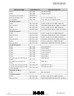
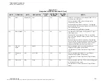
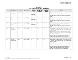
Components of the RDR-1700A Radar System are shown in Figure 1.0, and listed in Table 1.2-1, with
Telephonics part numbers and equipment type numbers.
Table 1.2-1
System Components
EQUIPMENT
TYPE NUMBER
TELEPHONICS
PART NUMBER
DESCRIPTION
RT-1501A 4001973-0151
Receiver-Transmitter
provides
X-band output signal to antenna. Pulses are 2.35 usec
at 200 PRF, 0.5 usec at 800 PRF, or 0.1 usec at 1600 PRF. Provides 10 kW peak
power output. Reflected signal is amplified by low-noise-figure (5 dB) solid-state
receiver, digitized and then routed to interface unit. Magnetron frequency (9375 ± 5
MHz) is trimmable to permit reliable triggering of the beacon transponder. In beacon
mode, beacon returns (9310 MHz) are amplified by a second receiver channel before
they are routed to interface unit. Unit contains self-test features. DC powered.
DA-1503B
071-01593-100
Antenna drive unit positions array in azimuth and elevation axes. Motor-driven with
combined pitch, roll and tilt line-of-sight stabilization, up to + 20°and - 30° of true
vertical for bottom-mount installation (+ 30° and - 20° for top-mount installation).
360° scan with selectable speeds of 45°/sec and 90°/sec. Stabilization in accordance
with pitch and roll signals from aircraft vertical gyro and CN-1506A Control Unit
TILT control. Tilt selectable ± 15° from horizontal. Mates withAA-1504A antenna
array.
IN-1502R
364-1000-001
The radar display has a 6.4 inches diagonal LCD display. This display has 18 soft keys
that control all radar functions. When a softkey is pressed, data is sent on the ARINC
429 data bus to the Interface Unit for command input. The Brightness Dimmer bus
shall have a voltage input from 0 to 5 Volts. A Rotary Switch on the front panel shall
provide the following selections: Power Off, Radar, and FLIR. The display shall also
have a Joystick with Enter Button for target selection.
The document reference is online, please check the correspondence between the online documentation and the printed version.

