Telephonics Corporation
R
A D A R
S
Y S T E M S
D
I V I S I O N
TM113806 (3/10)
1-9
1.3.2 Waveguide
Flexible or rigid waveguide may be used between the RT and the DA. The following types of
waveguide shall be used:
EIA WR90
MIL-W 85E
RG52/U (Copper/Bronze)
MIL-W 85E
RG67/U (Aluminium)
British WG16
IEC R100
The waveguide must have a cover flange on one end and a cover flange on the other.
Choke Flange with
Quick Disconnect
RT-1501A
DA-1503B
Cover Flange
Cover Flange
Choke Flange
Cover Flange
Cover Flange
Waveguide
Figure 1.3.2-1 Waveguide
Waveguide Electrical Specifications:
Loss
2.0 dB max
VSWR 1.4:1
max
Length
10 feet max
1.3.3 Radome
Radome kits and installation directions must be ordered directly from radome manufacturers or
supplied by the aircraft manufacturer. The radome provides a radar window for the radar signal.
Radome must have Transmissivity of 90% or better.
1.3.4
Attitude Heading and Reference System (AHRS)
The RDR-1700A Radar System requires aircraft attitude and heading information to stabilize the radar
antenna and to provide input to the tracker based upon aircraft movement. For complete AHRS
Interface specifications, contact Telephonics for the RDR-1700A Interface Control Document for the
364-0000-002 Configuration (P/N: 364-G621-ICD01).
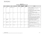
Table 1.3.4-1 lists the required ARINC 429 data.
The document reference is online, please check the correspondence between the online documentation and the printed version.


