Telephonics Corporation
R
A D A R
S
Y S T E M S
D
I V I S I O N
TM113806 (3/10)
2-33
2.6 POST-INSTALLATION
CHECK
WARNING:
Tests involving radiation of RF energy by the radar antenna must not be
made in the vicinity of refueling operations, or when personnel are standing
directly in front of the radar antenna. RF energy is generated in all modes
except standby and test. Do not allow personnel within the MEPL boundary
being scanned by antenna when system is transmitting.
Telephonics
recommends a safe distance of 7 feet (2.2 meters).
NOTE:
The following procedures can be performed efficiently by two persons with
a means of communication between them. One person should be stationed
in the cockpit, with the second person mobile, between the transmitter
location and the antenna. The radome should not be installed when
performing these procedures.
2.6.1 Visual
Inspection
(1) Check that waveguide, cabling and system components are mechanically and electrically secure.
(2) Check for free and proper operation of all controls.
(3) Check that primary power sources are functioning.
2.6.2
Initial Control Settings
(1)
Apply 28 VDC and 115VAC to the radar system.
(2)
Place the radar in Standby Mode.
2.6.3 Preliminary
Checks
(1)
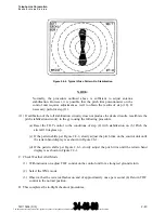
Change the RADAR mode TEST. After 60 to 90 seconds, a test pattern should appear on
indicator display. Adjust BRT control on indicator for a comfortable brightness level. Check that
the words RT FAULT appear along the right edge, and the word TEST appears in the upper left
corner of the display. Refer to the RDR-1700A Pilot’s guide for a typical test pattern. Check that
the test pattern color bands are in the sequence shown (width of the bands is not significant).
NOTE:
Optimum test pattern occurs in the 80-mile range.
(2) Check that the antenna drive unit scans 360 degrees and that update indication on the display
moves in synchronism and in the same direction as the antenna scan.
The document reference is online, please check the correspondence between the online documentation and the printed version.


