Telephonics Corporation
R
A D A R
S
Y S T E M S
D
I V I S I O N
2-34
TM113806 (3/10)
(3) Change the RATE to 90 deg/SEC is displayed along the left edge of the display. Antenna should
now scan at 7.5 rpm (45 degrees per second). Press rate pushbutton again to return antenna scan
rate to 15 rpm.
(4) At control unit, press STAB pushbutton. Check that antenna continues to scan, and the words
STAB OFF appear along the left edge of the display. Press STAB pushbutton again. The words
STAB OFF should disappear.
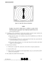
(5) At control unit, press HOLD pushbutton. The update indication should disappear, but the test
pattern should remain. Check that the antenna continues to scan and the word HOLD flashes on
and off in the upper left corner of the display.
(6) Press HOLD pushbutton again to deactivate the HOLD function. The test pattern update
indication should reappear.
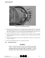
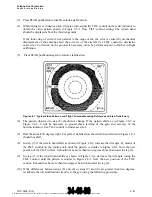
(7) Change the TILT control to +5 and then +15, checking that the antenna tilts upward smoothly and
without interference. (See Figure 2.6.4.3-3.)
(8) Adjust TILT control to -5 and then -15, checking that the antenna tilts downward smoothly and
without interference. Return TILT control to the 0 position. (See Figure 2.6.4.3-3.)
2.6.4
Antenna Stabilization Check
NOTE:
The following tests require accurate positioning of the vertical gyro in both
pitch and roll. If a tilt table is not available, the gyro may be positioned by
reference to the flight director or artificial horizon, or some other method of
accurately tilting the gyro in the aircraft. This calibration procedure should be
performed after any gyro or antenna maintenance.
2.6.4.1 Tilt Check
(a) Change the RADAR mode to STBY.
(b) Place the aircraft vertical gyro to zero degrees pitch and zero degrees roll.
(c) Set the TILT control on the control unit to position the antenna 0 degrees. The TILT control
setting should be 0 deg ±1 deg. (See Figure 2.6.4.3-3.)
(d) Set the TILT control to position the antenna to the 10-degree up reference mark. The TILT
control setting should be +10 deg ±1.5 deg. (See Figure 2.6.4.3-3.)
(e) Set the TILT control to position the antenna at the 10-degree down reference mark. The TILT
control setting should be -10 deg ±1.5 deg. (See Figure 2.6.4.3-3.)
2.6.4.2 Pitch Calibration Check
(a) Press the PITCH TRIM pushbutton on the control unit until the setting is at mid-range (16).
The document reference is online, please check the correspondence between the online documentation and the printed version.


