Telephonics Corporation
R
A D A R
S
Y S T E M S
D
I V I S I O N
TM113806 (3/10)
2-35
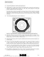
(b) With the RADAR mode set to STBY, manually position the antenna to zero degrees azimuth
using the Vernier scale on the antenna drive unit. (See Figure 2.6.4.3-2.)
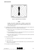
(c) Adjust the TILT control on the control unit to position the antenna exactly at zero degrees in
elevation. (See Figure 2.6.4.3-3.)
NOTE:
Do not make further adjustments to the TILT control until pitch and roll
calibration is completed.
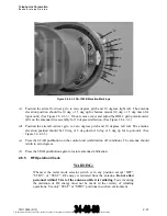
(d) Position the aircraft vertical gyro for 10 degrees nose up and zero degrees bank. The antenna
elevation position should be 10 deg ± 1.5 deg down. (See Figure 2.6.4.3-3.) If not, remove cover
and adjust the PITCH gain potentiometer (R4) on the antenna drive assembly for proper
deflection. (See Figure 2.6.4.3-1.)
NOTE:
Newer units of the DA-1503B now have pitch and roll adjustment holes within
the cover. If holes are present within the cover, then to not remove the cover,
but remove the hole covers. Once the pitch and roll adjustments have been
accomplished, replace the covers back over the holes.
(e) Position the aircraft vertical gyro for 10 degrees nose down and zero degrees bank. The antenna
elevation position should be 10 deg ±1.5 deg up. (See Figure 2.6.4.3-3.)
(f) Press STAB pushbutton on the control unit (stabilization off condition). The antenna should
return to zero degrees. (See Figure 2.6.4.3-3.)
(g) Press the STAB pushbutton again to restore antenna stabilization.
2.6.4.3 Roll Calibration Check
(a) Press the ROLL TRIM pushbutton on the control unit until the setting is at mid-range (16).
(b) With the RADAR mode set to STBY, manually position the antenna to 90 degrees using the
Vernier scale on the antenna drive unit. (See Figure 2.6.4.3-2.)
The document reference is online, please check the correspondence between the online documentation and the printed version.


