Telephonics Corporation
R
A D A R
S
Y S T E M S
D
I V I S I O N
TM113806 (3/10)
2-37
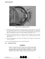
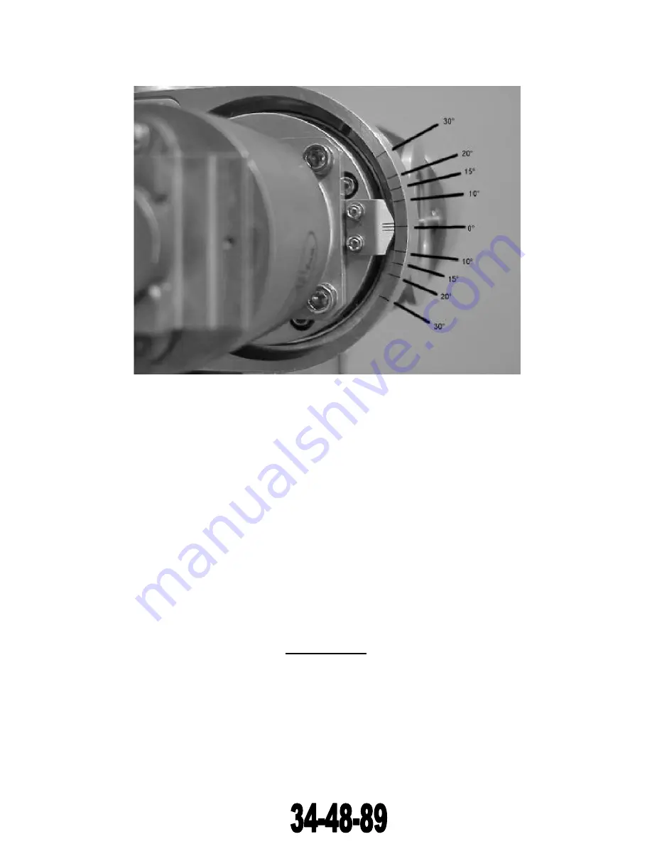
Figure 2.6.4.3-3 DA-1503B Elevation Markings
(c) Position the aircraft vertical gyro to zero degrees pitch and 10 degrees right roll. The antenna
elevation position should be 10 deg ± 1.5 deg up for bottom mount (10 deg ± 1.5 deg down for
top mount) (See Figure 2.6.4.3-3.). If not, remove cover and adjust the ROLL gain potentiometer
(R3) on the antenna drive assembly for 10 degrees deflection. (See Figure 2.6.4.3-1.)
(d) Position the aircraft vertical gyro to zero degrees pitch and 10 degrees left roll. The antenna
elevation position should be 10 deg ±1.5 deg down (10 deg ±1.5 deg up for top mount). (See
Figure 2.6.4.3-3.)
(e) Press the STAB pushbutton on the control unit (stabilization off condition). The antenna should
return to zero degrees.
(f)
Press the STAB pushbutton again to restore antenna stabilization.
2.6.5
RF Operation Check
WARNING:
Whenever the radar mode selector switch is in any position except “OFF”,
“STBY”, or “TEST”, RF energy is radiated from the antenna.
Do not allow
personnel within 15 feet of the antenna while it is radiating.
Tests involving
the radiation of RF energy must not be made in the vicinity of refueling
operations. Use only “TEST” or “STBY” positions in such an environment.
The document reference is online, please check the correspondence between the online documentation and the printed version.


