Telephonics Corporation
R
A D A R
S
Y S T E M S
D
I V I S I O N
TM113806 (3/10)
2-39
A. Energize the radar bus and vertical gyro reference bus. Ensure that 28 volts dc and 115 volts ac
power is being supplied to the system. Check that the vertical (stabilization) gyro is erected.
B.
Vary the external panel lighting voltage (dim control) for maximum panel brightness. Reduce the
lighting voltage. The panel lighting should dim.
C.
Set RADAR mode to TEST.
D. Check that the brightness (BRT) control on the indicator is set for a comfortable viewing level.
(The antenna TILT control may be set to any position.)
E.
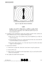
Note that RT FAULT appears along the right edge of the display. The word TEST should appear
in the upper left corner. The test pattern should appear on the indicator screen within 100
seconds. Adjust BRT control again, as required. Compare this test pattern as shown in the RDR-
1700A Pilot’s Guide.
NOTE:
The width of the test pattern bands is not critical, nor is the position of the
bands relative to the range marks.
(1) Set range to 80 NM. Check that the test pattern displays five colored bands. Starting with the
closest band to the origin, the bands will be green, yellow, red, yellow, and green. The red
band represents the most intense level. All range rings will be visible and displayed in blue.
(2) Observe the update action as a scanning line with its origin at the center of the CRT,
indicating that the antenna is scanning the full 360 degrees.
(3) Press the HOLD button. The update line should disappear and the test pattern should remain
stable. The word HOLD should flash in the upper left corner.
(4) Press the HOLD button again, and verify that update resumes.
NOTE:
Basically, the test pattern can be thought of as a weather target extending from
approximately 20 NM to 60 NM. Therefore, when in the TEST mode and
switching through the ranges, the test pattern position will be altered on the
screen.
F.
Change the range to 0.625 mile. The test pattern will be beyond the area being scanned. Increase
the range, one step at a time, and observe that the test pattern appears in the correct ranges.
Observe that the proper range and range marks appear in the display.
G. Set the RADAR mode to STBY, then taxi the aircraft to a clear-ahead area where metal
buildings, aircraft, etc., are not in the line-of-sight. Observe the warning at the beginning of
paragraph 2.6.
H. Change the RADAR mode to WX position. The indicator should display the legend WX in the
upper left corner.
The document reference is online, please check the correspondence between the online documentation and the printed version.


