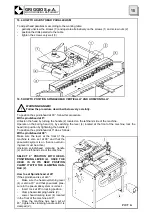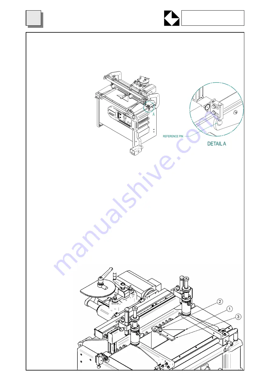
HOW TO USE CENTRAL SPLINE FOR STRAIGHT 90° FRAMES (optional)
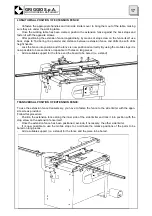
The spline is used to combine two pieces having 90°-angle sides (used mainly to make straight frames
rapidly)
-
Fasten the spline (3) in the reference holes on the working table and fasten it with the lever (2).
-
Position the pieces to be worked along the spline. It is now possible to start boring operations to as-
semble frames with “dowel” wooden stakes.
-
For a correct
position the spindle-
head must be at a
90° angle and the
hold down clamp
must be above the
piece to be bored.
Proceed as in a
standard working
cycle: press the con-
trol pedal to start the
cycle and release
the pedal at the end
of the cycle. Repeat
the procedure for
both sides of the
spline to obtain the
two bored parts of
the frame ready to
be joined.
16.8 HOW TO USE REFERENCE PIN FOR LINE BORING ON LARGE PIECES (optional)
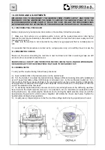
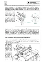
As it can be complicated to use the extension fence to bore large pieces, our machines comes with a
reference pin. This reference pin can be used for line boring on a large wood piece with higher axial dis-
tance between first and last drill than the one obtainable with this type of boring machine. The reference
pin is aligned with the drills
axis and it fits into a slot under
the machine table once the
first series of holes has been
bored. To continue boring op-
erations, the reference pin can
be used once again by turning
the knob to unlock the spring
that allows the reference pin to
come out. To make it possible
for another series of holes to
be bored, the reference pin
has to be inserted into one of
the holes that have just been
bored.
16.9 HOW TO USE TRIANGULAR FENCE FOR 45° FRAMES (optional)
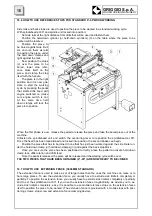
45° triangle can be very useful to manufacture 45°/45° frames very rapidly. Fasten the triangle on the
table in reference holes and clamp it in M8 central hole with the lever (2). In this way it is possible to lean
45-degree pieces to be bored and to join them with “dowel” wooden stakes. Machine spindlehead must
be set at 90°. When position is correct, the hold down clamp is over to piece to be worked. Proceed as
in a standard working cycle: press the control pedal to start the cycle and release the pedal at the end of
the cycle. Repeat the procedure on both sides of the triangle to obtain two specular frame pieces ready
to be joined.
GRIGGIO S.p.A.
WOODWORKING MACHINERY
18
Summary of Contents for GF 21
Page 2: ......
Page 4: ......
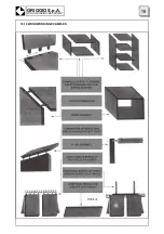
Page 23: ...16 10 WOODWORKING EXAMPLES 19 GRIGGIO S p A WOODWORKING MACHINERY ...
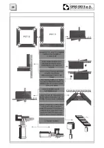
Page 24: ...GRIGGIO S p A WOODWORKING MACHINERY 20 ...
Page 33: ...29 GRIGGIO S p A WOODWORKING MACHINERY 26 SPARE PARTS CATALOGUE ...
Page 35: ...TABLE 1 FRAME 31 GRIGGIO S p A WOODWORKING MACHINERY ...
Page 37: ...TABLE 2 MACHINE TABLE 33 GRIGGIO S p A WOODWORKING MACHINERY ...
Page 39: ...TABLE 3 RACK 35 GRIGGIO S p A WOODWORKING MACHINERY ...
Page 41: ...TABLE 4 LIMITERS 37 GRIGGIO S p A WOODWORKING MACHINERY ...
Page 43: ...TABLE 5 SPINDLES UNIT 39 GRIGGIO S p A WOODWORKING MACHINERY ...
Page 45: ...TABLE 6 HOLD DOWN CLAMPS FRAME 41 GRIGGIO S p A WOODWORKING MACHINERY ...
Page 47: ...TABLE 7 BACK STOP 43 GRIGGIO S p A WOODWORKING MACHINERY ...
Page 49: ...TABLE 8 HOLD DOWN CLAMPS 45 GRIGGIO S p A WOODWORKING MACHINERY ...
Page 51: ...TABLE 9 SPINDLEHEAD 47 GRIGGIO S p A WOODWORKING MACHINERY ...
Page 53: ...TABLE 10 EXTENSION FENCE 49 GRIGGIO S p A WOODWORKING MACHINERY ...
Page 55: ......


