background image

20

but as far as signal quality is concerned you’re better off with a stable clock at an 
inexact frequency.

Jitter is not a problem in fully digital processes. As long as it isn’t so large that a 
processor can’t distinguish the previous bit from the next, all-digital processes are 
completely indifferent about jitter. The problem occurs when you go from the ana-
logue domain into the digital domain or back. Digital audio presumes uniform sam-
pling. That way, given a string of numbers and knowledge of the sampling interval, 
you can perfectly reconstruct a sampled signal. With jitter that theory falls flat on its 
back. 

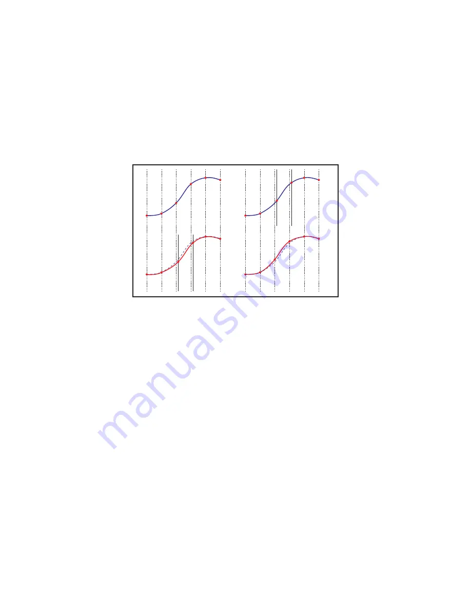
Imagine the signal on top. The AD converter samples it at neatly uniform intervals. 
The DA converter reconstructs the correct values but it gets the timing wrong. The 
difference between the red and blue curve shows the error. Or take the converse: 
the DAC is fine but the ADC took samples at the wrong time. The effect is much the 
same. What’s worse in this case is that the numbers we’ve recorded are now wrong. 
In the previous case we could slap in a better DAC, with a jittery ADC the game is 
over.

PLL’s

Converter chips need a high frequency clock signal, usually something around 
22MHz. It is always made by a local oscillator (anything from a simple RC oscillator 
in a receiver chip to a crystal oscillator) regardless of whether the unit is operating 
in master or slave mode. This local oscillator is indispensible: external sync sig-
nals may be AES/EBU, a sample rate frequency “word clock” or even a video signal, 
neither of which are of any direct use to the AD/DA. Instead, the local oscillator is 
sped up or slowed down to make it run in step with (“locked to”) the sync signal. A 
system that uses a local oscillator “pulled” in sync with an external signal is called 
a Phase Locked Loop (PLL). A “phase detector” compares the local clock with the 

Jitter in AD (top) and DA (bottom) converters

Summary of Contents for CC1

Page 1: ...Please read this manual before operating the unit ...

Page 2: ...TPInLB ...

Page 3: ...troduction 4 Important Safety Instructions 5 1 Installing 7 2 Signal Connections 8 3 Operation 8 4 Setting up the Studio 12 5 Pro Tools 16 6 Jitter and PLL s explained 18 7 Specifications 23 8 Grimm Audio Limited Waranty 25 ...

Page 4: ...of the reliable star distribution scheme The extremely low jitter of the CC1 clock outputs maximises the sound quality potential of the attached devices In case you need to slave your system to video clock please insert a Grimm Audio VCC video to word clock converter before the clock input Clock stability improvement and hence improved sound of digital live desks and digital snakes Clock distribut...

Page 5: ...uien a petición se encargaría de enviarle la correspondiente traducción Please follow these precautions when using this product 1 Read these instructions 2 Keep these instructions 3 Heed all warnings 4 Follow all instructions 5 Dangerous voltage is inside this apparatus Opening is only allowed by qualified service personnel 6 Verify line voltage before use 7 Do not defeat the safety purpose of the...

Page 6: ... with a cart stand bracket or table designed for use with professional audio or music equipment In any installation make sure that injury or damage will not result from cables pulling on the apparatus and its mounting If a cart is used use precaution when moving the cart apparatus combination to avoid injury from tip over 18 This unit runs slightly warm when operated normally Operate in a normal v...

Page 7: ... low level noise due to stray magnetic fields Grimm Audio products have a real wood face plate that provides a beautiful and vivid appearance To maintain the outstanding looks one is advised to take some precautions Do not place the CC1 in humid nor very dry environments The wood might crack Do not use chemical or alcohol based cleaner on the wood AC Power Hookup The CC1 has a linear power supply ...

Page 8: ...ry set line voltage value unlock behavior hold or mute 3 Operation Master mode The leftmost front panel pushbutton selects between two base clock rates 44 1kHz or 48kHz The two other pushbuttons determine the actual clock frequency trans mitted across the 16 BNC outputs They control in two groups Group 1 are chan nels 1 12 The second pushbutton sets the multiplication factor for this group to 1x 2...

Page 9: ...The presence of the aes signal has no effect In master mode with the aes dip switch set to mute any signal at the AES3 input is basically ignored except that the aes lock light on the rear will be on to indicate the presence of a synchronous input 4 A signal is applied to the AES3 input that is synchronous to the CC1 and the aes dip switch is set to thru The AES3 output fully copies audio and subc...

Page 10: ... AES3 signal instead The CC1 will never automatically switch from word sync to AES3 to prevent clock loops 4 No valid signal on either word sync or AES3 input The response is now deter mined by the dip switch named unlock When set to thru the clock frequency will be held constant within 1 ppm of the last valid measured frequency When set to mute the outputs will be muted In both cases the slave li...

Page 11: ...o duces a 6dB loss resulting in a 2 5V signal All Grimm Audio products are designed to work in this manner There is no standard defining word sync connections As a result impementations vary across makes Outputs may be series terminated or low impedance DC or AC coupled Inputs may be parallel terminated or high impedance This yields 8 permu tations all of them encountered in the wild The CC1 input...

Page 12: ...chronous This is what a house sync aka master clock is for Several formats are in use The AES promotes a standard called AES11 that uses an AES3 link but most equipment tends to use a word sync signal on a BNC connec tor The AES11 standard is to be amended to include this practice We think this is a good move since the purity of a clock recovered from an AES3 link is rather suscep tible to issues ...

Page 13: ...edance reference plane at the rear insuring that it will never be affected by circulating currents Not all equipment is designed in this manner In case your system holds interfacing equipment that is sensitive to ground loops Grimm Audio has an isolation transformer available on demand CI1 Such devices degrade clock quality somewhat so they should be avoided when driv ing equipment of which the AD...

Page 14: ...cillator that forms part of its PLL If the incoming clock happens to be much stabler than that the slow mode will actually end up adding jitter The latter scenario is almost guaranteed to be the case with the CC1 which is significantly cleaner than any clock oscillator we ve found in commercially available audio products so far As a rule in this case it is usually better to select the fast mode In...

Page 15: ...nc you can either buy our VCC Video to Word Clock con verter or use any other generic video to word clock converter Connect the retreived word clock to the CC1 s word clock input and have the CC1 clean up the sync and distribute clock to the audio devices as usual The extraordinary stability of the CC1 s PLL will make sure the result comes as close as possible to making the audio chain master Hint...

Page 16: ... by fooling the system into believe that Loop Sync is in use while actually a star clock distribution is utilized Star clock distribu tion has the advantage that it is more fail safe than daisy chaining and jitter gain of subsequent PLL s is avoided Connect an output of CC1 s group 2 to the External Word Clock input of the first unit in the chain if present the Sync I O otherwise the first 192 Con...

Page 17: ... just for time code synchronisation The word clock connections are as described in the former paragraphs Pro Tools in music production Special attention is needed for the time code connection Up till Pro Tools 8 there was no way of combining the Sony P2 Machine Control time code signal with an external word sync like the CC1 Selecting Sony P2 forced the Sync I O to slave to video sync With current...

Page 18: ...ithin one second This is the preferred method b Pro Tools is controlled directly by its transport buttons The external machine locates and gets into play through Sony P2 locator commands The user selects a cue point and hits play The external machine will rewind to this time code minus a pre roll and starts rolling Pro Tools waits until it sees the correct time code coming back Pro Tools slaves to...

Page 19: ...find energy frequency frequency Amplitude Amplitude Jittery clock Jitter free clock slightly off the ideal frequency The red curve in the bottom graph shows only random jitter Sometimes jitter is periodical and then you wouldn t see a smooth slope but sharp peaks An im portant note is that frequency accuracy has absolutely nothing to do with jitter at all The red graph shows a jittery clock with a...

Page 20: ...ake the converse the DAC is fine but the ADC took samples at the wrong time The effect is much the same What s worse in this case is that the numbers we ve recorded are now wrong In the previous case we could slap in a better DAC with a jittery ADC the game is over PLL s Converter chips need a high frequency clock signal usually something around 22MHz It is always made by a local oscillator anythi...

Page 21: ...rnal sync signal Above the cut off point the PLL will not reproduce any errors present in the input but neither will it be able to cor rect errors committed by its own local oscillator Here s the transfer of a basic PLL designed to have a cut off frequency of 4kHz Mark that in this graph we are not looking at audio frequencies but at jitter or fluctuation frequencies The blue curve shows the atten...

Page 22: ... Alternatively a too slow PLL might not correct a local oscillator of suboptimal qual ity In that case jitter performance is bad regardless of the quality of the external clock And here lies the rub a slow PLL will always make a converter sound the same but not necessarily good If a converter is insensitive to external jitter that alone is no indication that its internal jitter is low A slow PLL s...

Page 23: ...channels Word clock output voltage terminated 2 7 Vpp unterminated 5 5 Vpp DC coupled Latency word clock in word clock out adjusted to less than 50 ns but may be larger due to input clock jitter Internal intrinsic clock jitter 2 1 ps RMS above 10 Hz Clock frequency master mode 1 2 or 4 times 44 1 or 48 kHz 10 PPM 5 50 C PLL performance slave mode 90 dB attenuation 10 Hz improving at 60 dB dec abov...

Page 24: ...24 Grimm Audio contact information Grimm Audio CV Strijpsestraat 94 5616 GS Eindhoven The Netherlands 31 0 40 213 1562 Email info grimmaudio com Website http www grimmaudio com ...

Page 25: ...Audio or an authorized Grimm Audio repair facility postage prepaid insured and properly packaged Proof of purchase must be presented in the form of a bill of sale or some other positive proof that the product is within the warranty period Grimm Audio reserves the right to update any unit returned for repair Grimm Audio reserves the right to change or improve design of the product at any time witho...

Page 26: ...26 ...

Page 27: ......

Page 28: ......

Reviews: