Beijing Grinder Instrument Co., Ltd. Tel
:
010-82363430
Fax
:
010-82363435
20
M2-5
M2-3
G
M2-1
M2-4
P
O
K
H
pcs hexagon socket head screws
(
M5×12), then seal the hopper with cover
O
and screw
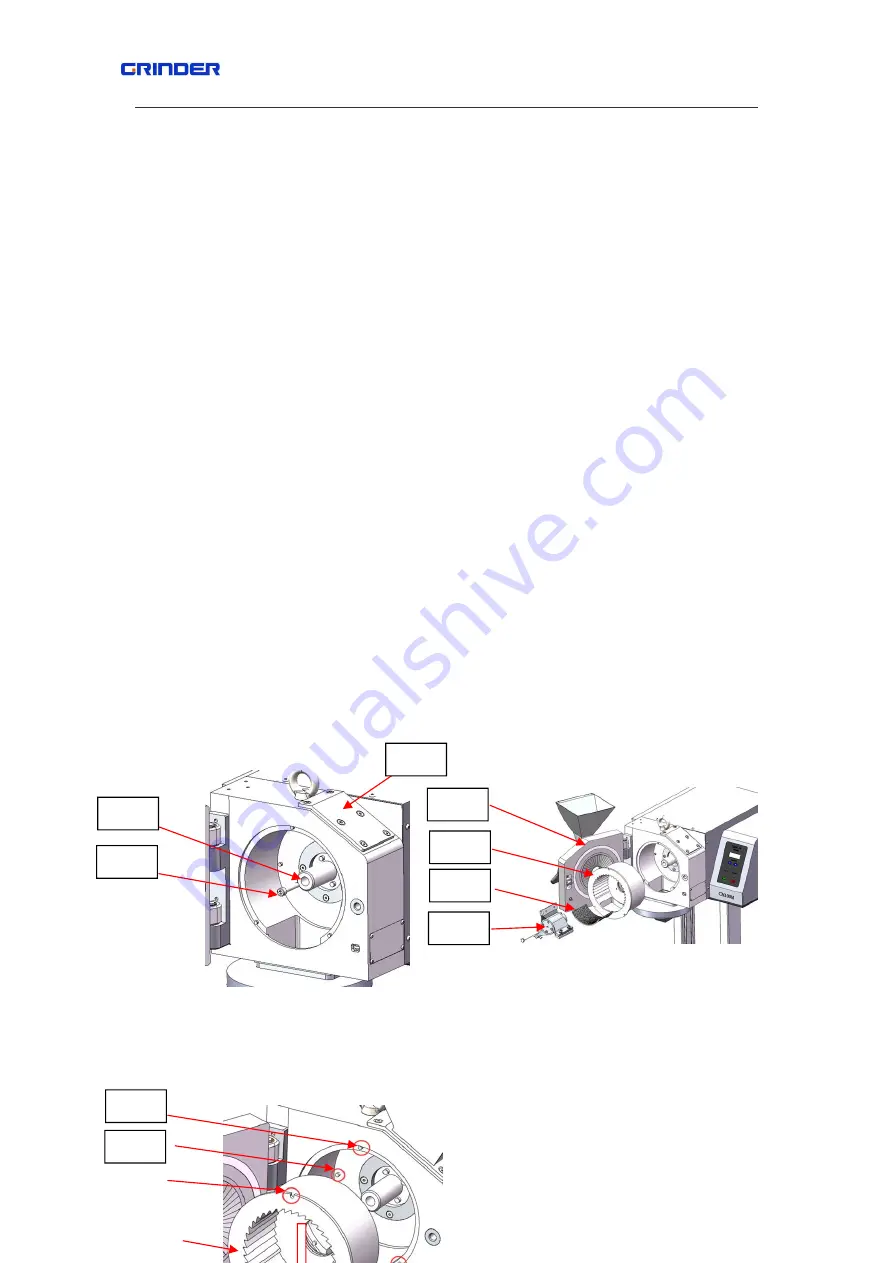
them with 4 screws,refer to fig
5.5.1
Second step
:
remove the rotor
M1-3 from M1
manually.
Third step
:
remove the fixed screw P :loosen and remove the screw P from axle X with
supplied 6mm hexagon socket wrench in anticlockwise direction.Refer to fig
5.5-1
Forth step
:
remove the door of M1 and left M1-1,then replace it.
Fifth step
:
install M2 door
:
install the M2-1(the door ,hopper and grinding accessories of
M2-2) to the hinge of grinding chamber,refer to fig
5.5-2
Sixth step:
Install the parts of M2-4:please align the slot Q(3 places totally) with limited
post G(3 places totally),and the outlet port R match to the bottom outlet of M2 and turn it to
the innermost position,the 2 limited holes should insert to the limited post H when with
right position.Refer to fig
5.5-2~5.4-4
Seventh step
:
install the cross beater rotor M2-3
:
insert the M2-3 into the axle K and
press it into innermost place and fix the M2-3 to the drive shaft K with a pc of hexagon
head screw T(M8×90),refer to fig
5.5-5
Eight step
:
Install the bottom sieves
:
place
M2-5
at the bottom of
M2-4
Note
:
Replace the accessories with opposite order.
Fig
5.5.1
fig 5.5.2


