Beijing Grinder Instrument Co., Ltd. Tel
:
010-82363430
Fax
:
010-82363435
22
M2-1
M3-1
U
U
T
M2-4
H
V
G
V
M2-3
M3-4
M2-5
U
M3-3
T
M3-3
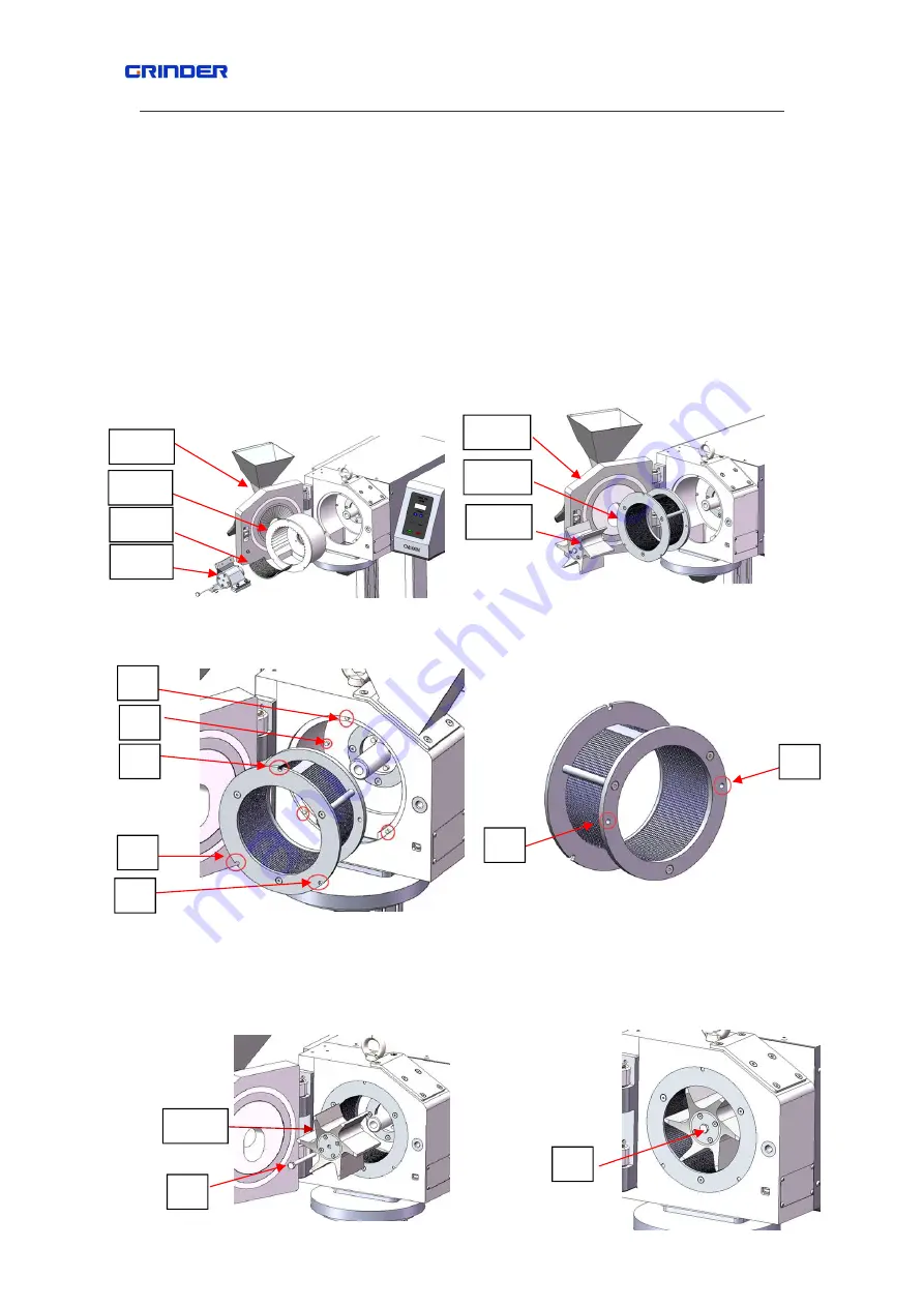
limited post G(3 places totally), turn it to the innermost position with both hands,the 2
limited holes V should insert to the limited post H when with right position.Refer to fig
5.6.2~5.6.4
Sixth step
:
Install the rotor of M3-3
:
insert the M3-3 into the axle K and press it into
innermost place and fix the M3-3 to the drive shaft K with a pc of hexagon head screw
T(M8×90),refer to fig
5.6.5~5.6.6
Note
:
replace the grinding accessories with opposite order.
Fig 5.6.1
fig 5.6.2
M3-3
Fig
5.6.3
fig 5.6.4


