Beijing Grinder Instrument Co., Ltd. Tel
:
010-82363430
Fax
:
010-82363435
27
1
2
3
4
6
4
9
10
8
7
5
7
8
9
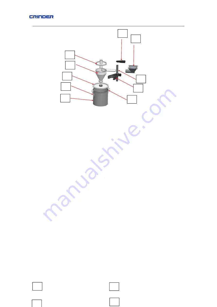
10.outlet ring
Fig
5.17.1
5.17.2 Installation notes
:
fig .17.2.1~5.17.2.2
First step
:
fasten the supplied bar 7 to the fixed set 9 with one pc of
hexagon socket head
screws M6x20
Second step
:
Install the fixed set 9 and the supplied bar 7 on the main body and fasten them with
4 pcs of hexagon socket head screws M4x8.
Third step
:
Install the supplied handle 6 on the supplied bar 7.
Forth step
:
fixing the outlet hopper 8 onto the outlet ring 10 with
4 pcs of hexagon socket
head screws M4x8 refer to fig
5.17.2.1
Fifth step
:
Insert the feed hopper 2 into the round hole of outlet hopper 8 and adjusted with
available height and fasten them with hand wheel.
Sixth step
:
install the cover 3 to the hopper 2 (thread connection)
Seventh step
:
fix the bucket 5 with 3 pcs of hang locks.
Eighth step
:
put the cover 1 to the hopper 2 and press 1 down to ensure seal up them well.
Assembled them with opposite order.
Note
:
please insert the exhaust tube of
vacuum cleaner into the interface of cover 1 when
connect a vacuum cleaner.


