background image

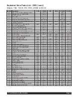
Exploded View Parts List - 230V (cont.)

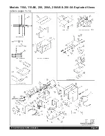
Models 115A, 115AB, 250, 250A, 250AB & 250-3A 

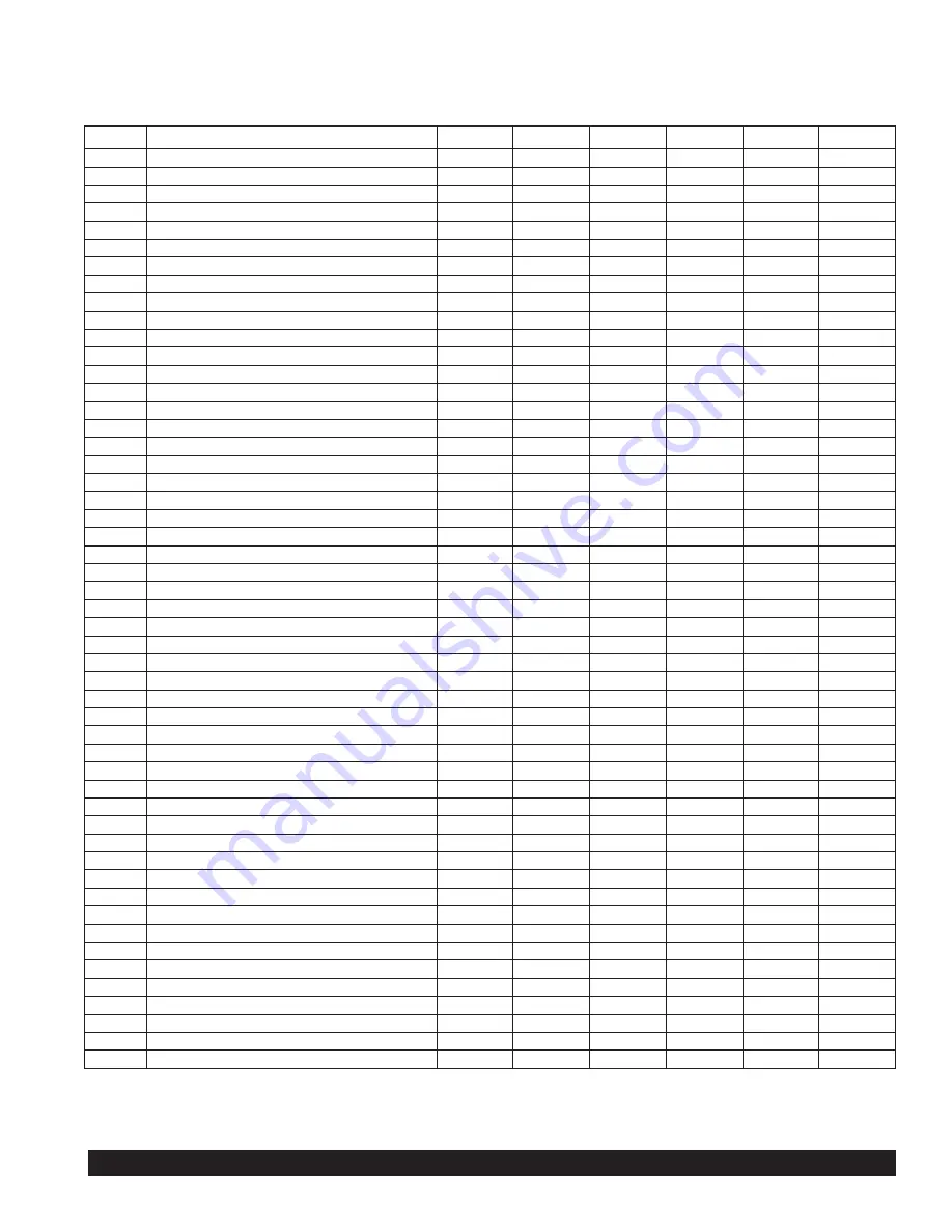
Item No. Description

115A

115AB

250

250A

250AB

250-3A

56

NUT, 1/4-20 X 7/16 HEX JAM ZINC PLATED

86892

86892

57

WASHER, FLAT 1/4 - ZINC PLATED

86824

86824

58

SPRING, TENSION

86118

86118

59

SHIFT, ARM

86114

86114

60

SCREW, 1/4-20 X 3/4 THUMB ZINC

86089

86089

61

SOLENOID, GRIND SHIFT 230V 50HZ

86534-02K

86534-02K

62

SCREW, #8 X 1/4 PH TR HD SMS T/B 410 SS

89116

89116

89116

89116

89116

89116

63

HARNESS, SOLENOID

86048

86048

64

PIN, COTTER 3/32 X 1 ZINC PLATED

86853

86853

86853

86853

86853

86853

65

BRACKET, SOLENOID MTG

86116

86116

66

NUT, 8-32 KEPS ZINC PLATED

86810

86810

67

ASSEMBLY, GRIND SHIFT HINGE A225-28-1

86107

86107

68

SCREW, 8-32 X 1/2 PH TR ZINC

86809

86809

69

SCREW, #8 X 1/4 PH TR HD SMS T/B 410 SS

89116

89116

89116

89116

89116

89116

70

SCREW, 5/16-18 X 1 SL FIL HD M/S

86819

86819

71

PLATE, FRONT

86007

86007

86007

86006

86006

86006

72

SWITCH, DECAF / REGULAR ROCKER

86075

86075

86075

86075

73

SWITCH,PORTION ROCKER 

86075

86075

86075

86075

83231

74

SWITCH, ROCKER START

70445

70445

70445

70445

70445

70445

75

CAPACITOR, 230V W/ BRACKET

86179

86179

86179

86179

86179

86179

76

SCREW, 8-32 X 1/2

86808

86808

86808

86808

86808

86808

77A

SPRING

86141

86141

86141

86141

86141

86141

77

SPRING, CHAFF MIXER

86146

86146

86146

86146

86146

86146

77

SPRING, W/ CHAFF SUPPRESSION

86235

86235

86235

86235

86235

86235

78

SCREW, 4-40 X 1/4 PH PN HD ZINC

86148

86148

86148

86148

86148

86148

79

DEFLECTOR

86220

86220

86220

86220

86220

86220

80

GASKET, PROPORTIONER TO HEAD

71419

71419

71419

71419

71419

71419

81

STANDOFF, REVERSE EDGEMOUNT

61266

61266

61266

61266

61266

61266

82

SPOUT

86218

86218

86218

86218

86218

86218

83

SCREW, 8-32 X 3/8 PH RD HD

86217

86217

86217

86217

86217

86217

84

BRACKET, CONTROL BOARD

86038

86038

86038

86038

86038

86038

85

BOLT, 1/4-20 HX HD

86872

86872

86872

86872

86872

86872

86

BUSHING, HEYCO OPEN / CLOSED

86039

86039

86039

86039

86039

86039

87

DIGITAL, TIMER

86139

86139

86139

86139

86139

86139

88

SPRING, BASKET ARM

86508

86508

86508

86508

86508

86508

89

NUT, WHIZLOCK 1/4-20

87049

87049

87049

87049

87049

87049

90

SPACER

87026

87026

87026

87026

87026

87026

91

ARM, BASKET LEFT

71014

71014

71014

71014

71014

71014

92

ARM, BASKET RIGHT

71013

71013

71013

71013

71013

71013

93

SCREW, 5/16 X 1 HEX SOC SHLDR

87024

87024

87024

87024

87024

87024

94

SPACER

87025

87025

87025

87025

87025

87025

95

CASING

86011K

86011K

86012K

86012K

86012K

86012K

96

CIRCUIT BREAKER, 5A

83107

83107

83107

83107

83107

83107

97

POWER CORD, 1.5MM CE

61453

61453

61453

61453

61453

61453

98

STRAIN RELIEF

86071

86071

86071

86071

86071

86071

99

SCREW, 8-32 X 3/8 PH T/H 410SS

82097

82097

82097

82097

82097

82097

100

PLATE, LOWER FRONT

86003

86003

86003

86003

86003

86003

101

PLATE, SAFETY SHIELD

87032K

87032K

87032K

87032K

87032K

87032K

102

MOTOR MOUNT ASSEMBLY

86995

86995

86995

86995

86995

86995

103

SCREW, 10-32 X 5/16 SL BD HD M/S ZINC

86812

86812

86812

86812

86812

86812

104

WASHER, LCK #8 INT ZNC PLTD

86822

86822

86822

86822

86822

86822

115 & 250 Series Coffee Grinders

Page 14

Summary of Contents for 115

Page 1: ...eaning Instructions 6 Removal and Reinstallation of Upper Hopper Assembly 6 Shear Disc Replacement 7 Troubleshooting Guide 8 9 Exploded Views 10 18 Wiring Diagrams 19 22 Grindmaster Corporation 4003 Collins Lane Louisville Kentucky 40245 USA 502 425 4776 800 695 4500 USA Canada only 800 568 5715 Technical Service FAX 502 425 4664 www grindmaster com Grindmaster Corporation 1998 Printed in the USA ...

Page 2: ......

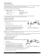
Page 3: ...echnical Service Department for help 502 425 4776 or 800 695 4500 USA Canada only 8 AM 6 PM EST Instructions Your new coffee grinder is easy to operate and maintain Before you place it in service please have all personnel familiarize themselves with these instructions then keep this manual in a convenient place for ready reference Set up Procedures 1 You the user must determine the quantity of cof...

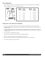
Page 4: ...ton lowers the displayed value the right button increases the displayed value The time values are set in seconds and tenths of a second 4 Refer to chart above for approximate timer settings Note For accuracy you must weigh the coffee and make appropriate adjustments 5 In order to store this desired value you must press the grinder start switch once Note If start switch is not pushed the last value...

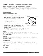
Page 5: ...ser see Figure B We recommend that you do not turn the adjusting screw more than two notches on the scale before testing the new grind setting NOTE Be sure that when adjusting the grind that you do not adjust too fine causing the burrs to touch each other a sound of metal scraping metal This could cause damage to the burrs or motor 5 After the adjustment has been made tighten adjusting screw lock ...

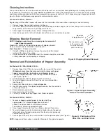
Page 6: ...made tighten Adjusting Screw Lock Nut 5 To visually inspect grind adjustment test grind a small portion of coffee and re adjust if necessary Note Adjusting the grind may alter the portion of coffee dispensed After grind adjustment weigh portion and adjust if necessary see How to Adjust the Portion Current It is absolutely essential that full voltage and amperage always be available as it takes ful...

Page 7: ... Reinstallation of Hopper Assembly For Models 250 250A 250AB 250 3A 1 Remove Upper Front Plate by removing the four screws in the corners Shipping bracket must be removed prior to removal of upper hopper assembly See instructions and diagram above 2 Lift Upper Hopper Assembly while rotating the Assembly slightly upward see Figure F 3 Pull the Assembly forward toward front of unit and out 4 To rein...

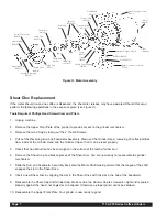
Page 8: ...he grinder mechanism 7 Slide the Burr and Feedworm Assembly back onto the Motor Shaft making certain that the tongue of the shaft engages the slot in the Shear Drive 8 Insert a new Shear Disc by aligning the slot in the Shear Drive with the slot in the hub of the Feedworm 9 Reassemble the Shear Cap and Grinder Cap Make certain the Grinder Cap is screwed on tight and is sealed properly against the ...

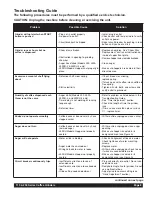
Page 9: ... each throw is not the same Auger stalls Models 250 250A 250RH 2 and 250RH 3 only Timer delay is not working or running long enough Defective timer Refer to problem as listed below in this Troubleshooting Guide See Timer Adjustment section Check the length of time the grinder runs If time varies more than plus or minus 1 replace timer Knobs do not operate smoothly Coffee beans or bean dust may hav...

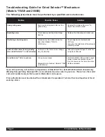
Page 10: ...se Burrs are touching each other on fine grind setting Readjust fine grind setting see To Adjust Fine Grind section Rumbling noise Thrust bearing rotating inside flange bearing Replace thrust bearing and shear cap Chattering or buzzing noise Solenoid may have failed to seat or close fully Models 115AB 250AB only Check alignment of solenoid and shift arm Also check the tightness of the solenoid mou...

Page 11: ...115 250 Series Coffee Grinders Page 10 Models 115A 115AB 250 250A 250AB 250 3A Exploded Views refer to pages 11 14 ...

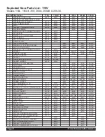
Page 12: ... 01 83141 01 83141 01 27 HOPPER AUGER W SPOUT 83150 83150 83150 83150 28 ADAPTER DRIVE 80019 80019 80019 80019 29 SPRING AUGER 86046 86046 86046 86046 30 FUNNEL AUGER 83134 83134 83134 83134 31 MOTOR AUGER 115V 86050 86050 86050 86050 32 BRACKET MOTOR 86042 01 86042 01 86042 01 86042 01 33 GASKET HOPPER 83081 83081 83081 83081 34 NUT TINNERMAN 1 4 20 86864 86864 86864 86864 86864 86864 35 MOTOR 1 ...

Page 13: ...5 86235 78 SCREW 4 40 X 1 4 PH PN HD ZINC 86148 86148 86148 86148 86148 86148 79 DEFLECTOR 86220 86220 86220 86220 86220 86220 80 GASKET HOPPER FUNNEL 83105 83105 83105 83105 83105 83105 81 STANDOFF REVERSE EDGEMOUNT 61266 61266 61266 61266 61266 61266 82 SPOUT 86218 86218 86218 86218 86218 86218 83 SCREW 8 32 X 3 8 PH RD HD 86217 86217 86217 86217 86217 86217 84 BRACKET CONTROL BOARD 86038 86038 ...

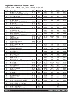
Page 14: ...1 27 HOPPER AUGER W SPOUT 83150 83150 83150 83150 28 ADAPTER DRIVE 80019 80019 80019 80019 29 SPRING AUGER 86046 86046 86046 86046 30 FUNNEL AUGER 83134 83134 83134 83134 31 MOTOR AUGER 230V 86000 86000 86000 86000 32 BRACKET MOTOR 86042 01 86042 01 86042 01 86042 01 33 GASKET HOPPER 83081 83081 83081 83081 34 NUT TINNERMAN 1 4 20 86864 86864 86864 86864 86864 86864 35 MOTOR 1 2HP 230V 50 HZ 86421...

Page 15: ...8 86148 86148 86148 86148 86148 79 DEFLECTOR 86220 86220 86220 86220 86220 86220 80 GASKET PROPORTIONER TO HEAD 71419 71419 71419 71419 71419 71419 81 STANDOFF REVERSE EDGEMOUNT 61266 61266 61266 61266 61266 61266 82 SPOUT 86218 86218 86218 86218 86218 86218 83 SCREW 8 32 X 3 8 PH RD HD 86217 86217 86217 86217 86217 86217 84 BRACKET CONTROL BOARD 86038 86038 86038 86038 86038 86038 85 BOLT 1 4 20 ...

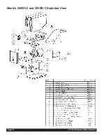
Page 16: ...Page 15 115 250 Series Coffee Grinders Models 250RH 2 and 250RH 3 Exploded View ...

Page 17: ...115 250 Series Coffee Grinders Page 16 Models 250RH 2 and 250RH 3 Removable Hopper Exploded View Models 250RH 2 and 250RH 3 Casing Assembly Exploded View ...

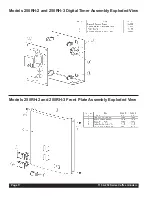
Page 18: ...Page 17 115 250 Series Coffee Grinders Models 250RH 2 and 250RH 3 Digital Timer Assembly Exploded View Models 250RH 2 and 250RH 3 Front Plate Assembly Exploded View ...

Page 19: ...115 250 Series Coffee Grinders Page 18 Models 250RH 2 and 250RH 3 Motor Mount Assembly 120V Exploded View Models 250RH 2 and 250RH 3 Auger Motor Mount Assembly Exploded View ...

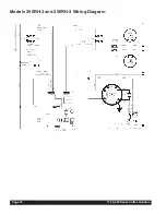
Page 20: ...Models 250RH 2 and 250RH 3 Wiring Diagram Page 19 115 250 Series Coffee Grinders ...

Page 21: ...115 250 Series Coffee Grinders Page 20 115A 115AB 250 Series Wiring Diagram 115V ...

Page 22: ...115A 115AB 120V Wiring Diagram Page 21 115 250 Series Coffee Grinders ...

Page 23: ...115 250 Series Coffee Grinders Page 22 115A 115AB 120V Wiring Diagram ...

Page 24: ...everage Dispensers Crathco Cold and Frozen Beverage Dispensers AMW Coffee and Tea Systems Tel 502 425 4776 Fax 502 425 4664 1 800 695 4500 USA Canada only P O Box 35020 Louisville KY 40232 USA www grindmaster com email info grindmaster com 0108 Form GR 373 04 Part 85358 Grindmaster Corporation 1998 PRINTED IN USA ...

Reviews: