COMPONENT REPLACEMENT INSTRUCTIONS
WARNING
- Disconnect power before servicing. Risk of electric shock.
These steps apply to replacement of TANK, TANK HEATER, and HI-LIMIT or MAIN THERMOSTAT
1. Remove brewer lid. Disconnect electrical connectors from upper warmer plate if applicable.
2. Remove pour in basin assembly (receiving pan).
3. Disconnect electrical terminals and hoses as needed.
4. Remove front two screws mounting the tank.
5. Lift tank and lid completely out of tank.
6. Remove two rear screws mounting tank to tank lid.
7. Reverse steps 1-6 to reassemble new tank assembly.
THERMOSTAT, HI-LIMIT
1. Disconnect wires to hi-limit thermostat.
2. Remove two screws and remove thermostat.
3. Check continuity of the new hi limit thermostat before installing.
4. Screw down new t-stat and reconnect wires.
5. Make sure the hi-limit thermostat is securely mounted and that all electrical connections are tight and isolated.
MAIN THERMOSTAT
1. Disconnect wires and remove tank and tank lid assembly.
2. Remove two rear screws mounting tank to tank lid.
3. Remove screws which secure thermostat to tank lid.
4. Loosen thumb nut securing capillary bulb.
5. Remove grommet from top of tank lid by pressing up with thumb and pulling capillary bulb out through hole.
6. Reverse steps 1-5 to reassemble new tank assembly.
TANK HEATING ELEMENT
1. Disconnect wires and remove tank and tank lid assembly.
2. Remove two rear screws mounting tank to tank lid.
3. Loosen thumb nut securing capillary bulb and remove bracket.
4. Remove two brass nuts and remove element.
5. Install new element and washers with nuts secured tightly.
6. Inspect tank lid gasket and replace if necessary.
7. Reverse steps 1-3 to reassemble.
WARMER ELEMENT
1. Remove retaining screws from warmer plate.
2. Lift plate and disconnect leads.
3. Remove nuts and washers holding retaining plate and warmer element to plate.
4. Reverse steps 1-3 to reassemble.
Auto Series Brewer Manual
Page 14
Summary of Contents for AT-2W
Page 2: ......
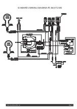
Page 15: ...Auto Series Brewer Manual Page 15 SCHEMATIC WIRING DIAGRAM AT 2W AT 2WE ...
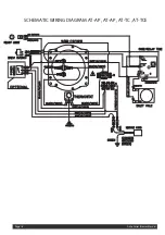
Page 16: ...Auto Series Brewer Manual Page 16 SCHEMATIC WIRING DIAGRAM AT AP AT AP AT TC AT TCE ...
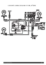
Page 17: ...SCHEMATIC WIRING DIAGRAM AT 3WR AT 3WRE Auto Series Brewer Manual Page 17 ...
Page 18: ...Auto Series Brewer Manual Page 18 SCHEMATIC WIRING DIAGRAM AT 3W AT 3WE ...
Page 19: ......

