background image

INSTALLATION INSTRUCTIONS

1) Place the decanter under brew basket, raise top evaporation cover and pour three decanters of water through the

top pour-in opening. Water should come through the brew basket as the third decanter of water drains out of the 
pour-in basin.

2)  Brewer is shipped with thermostat turned on, (full clockwise position). Plug brewer into a dedicated, grounded 

120V/15A circuit (230V/15A circuit for E models).

3) Allow 10-15 minutes for water in tank to heat to brewing temperature. (Hot water may drip from brew basket on 

initial thermal expansion of water in the tank). This will not occur thereafter.

4)  After water has reached brewing temperature (thermostat will click off, heating noise will stop and green ready light 

will be on) pour 1 decanter (60 oz./1.8L) of water through pour-in opening. Machine is now ready to use.

5) Pour 1 decanter of water through pour-in opening to check for proper temperature setting with an accurate 

thermometer. Take the temperature of this water at a point below the brew basket opening at the start of the brew 
cycle and when the decanter is half full. Recommended temperature of the water is approximately 195°F (91°C) .

6) In higher altitude locations (5,000 feet/1,500m above sea level) the thermostat may have to be adjusted lower to 

prevent boiling.

WARNING

- Read and follow installation instructions before plugging or wiring in machine to electrical circuit. 

Warranty will be void if unit is connected to any voltage other than that listed on the name plate.

FILL BREWER TANK WITH WATER BEFORE CONNECTION TO POWER SUPPLY

WATER CONNECTION

The following is required for water hook-up:
1)   A quick disconnect water connection or enough coiled tubing so the machine can be moved for cleaning 

underneath. (

required for NSF approved water hook-up

)

2)   A 1/4" male flare adapter is provided to be attached by the installer to the back of the machine for hook-up to 

water supply. 

3)   Installation to a water filter system is required to prevent lime and scale build up in the machine. 
4)   Water pipe connections and fixtures directly connected to potable water supply shall be sized, installed, and 

maintained in accordance with Federal, State, and Local codes. (

required for NSF approved water hook-up

)

5) Equipment is to be installed with adequate backflow protection to comply with applicable Federal, State,    

and local codes. (

required for NSF approved water hook-up

)

Minimum water pressure to the machine: 30 psi (2.0 bar)                                                                        
Maximum water pressure to the machine: 80 psi (5.6 bar)

Page 4

Auto Series Brewer Manual

Summary of Contents for AT-2W

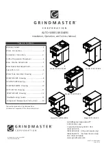
Page 1: ...T 2W AT 2WE Drawing 8 AT AP AT APE Drawing 9 AT 3WR AT 3WRE Drawing 10 AT TC AT TCE Drawing 11 Troubleshooting Guide 13 Component Replacement Instructions 14 Grindmaster Corporation 2007 PRINTED IN THAILAND 0307 Form BW 340 02 Part 73254 Prior authorization must be obtained from Grindmaster Corporation for all warranty claims Grindmaster Corporation 4003 Collins Lane Louisville Kentucky 40245 USA ...

Page 2: ......

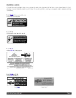
Page 3: ... your labels is missing or damaged order a replacement label immediately Part 71509 for warmer models only Located near warmer plates Part 71582 Located on rear and top access panels Part 70248 Located on front behind server Part 71949 or 71149 Located on brew basket CAUTION Remove with care Hot liquid in brew basket could cause burns Part 71949 Auto Series Brewer Manual Page 3 Part 71149 ...

Page 4: ... 6 In higher altitude locations 5 000 feet 1 500m above sea level the thermostat may have to be adjusted lower to prevent boiling WARNING Read and follow installation instructions before plugging or wiring in machine to electrical circuit Warranty will be void if unit is connected to any voltage other than that listed on the name plate FILL BREWER TANK WITH WATER BEFORE CONNECTION TO POWER SUPPLY ...

Page 5: ...he brew basket and turn corresponding warmer switch ON NOTE For airpots open airpot lid remove pump stem from airpot and place airpot opening directly under center hole in brew basket 5 Press Brew switch once then release 6 Valve will turn on approximately 1 minute and fill pour in basin 7 Hot water will be delivered through the sprayhead This distributes the hot water evenly over the coffee bed w...

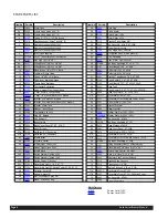
Page 6: ...1 2 Manual Reset 230V Models 57A 73321 1 Decal Main Front AT 2W 18 62238 Bracket Hi Limit 120V Models 57B 73321 Decal Main Front W Switch Power AT 2W 100524 Bracket Hi Limit Manual Reset 230V Models 58 73031 Panel Warmer Top AT 2W 19 73095 Bracket Water Tank 59 73001 Bracket Warmer 20 73057 Gasket Tank O Ring 60 73002 Plate Warmer 21 73096 Thermostat Clip Lock 61 13029 Heater Warmer 120V 100W 22 6...

Page 7: ...WATER TANK ASSEMBLY Auto Series Brewer Manual Page 7 6 1 1 2 1 A 2 4 6 5 7 8 A 9 0 1 B 9 1 1 2 1 3 1 4 1 5 1 3 B 2 2 2 0 2 9 1 8 1 7 1 B 2 3 ...

Page 8: ...al AT 2W AT 2WE PART LIST 6 7 B 2 3 2 4 2 6 5 8 2 B 7 2 A 7 5 9 2 0 3 1 3 A 7 2 4 5 3 5 0 5 3 6 7 4 5 4 2 6 4 4 3 4 0 4 1 4 9 3 7 3 6 3 5 3 4 3 8 5 9 5 1 6 0 6 B 7 5 B 2 3 8 3 A 2 3 A 2 3 9 6 0 7 1 7 2 7 3 1 4 1 4 7 3 7 5 7 6 4 5 5 ...

Page 9: ...LIST Auto Series Brewer Manual Page 9 3 1 4 1 3 2 4 2 5 2 6 2 8 2 A 3 3 9 2 0 3 1 3 A 7 2 1 5 9 4 0 5 2 5 8 4 7 4 5 4 2 4 4 4 3 4 0 4 1 4 9 3 7 3 6 3 5 3 4 3 B 7 2 B 3 3 B 2 3 8 3 9 6 0 7 1 7 2 7 4 7 3 7 5 7 6 7 B 2 6 4 ...

Page 10: ...uto Series Brewer Manual 4 1 3 1 3 2 5 6 8 2 A 7 6 B 7 2 9 2 0 3 1 3 A 2 3 A 7 2 4 5 3 5 0 5 5 5 8 6 7 4 5 4 2 4 4 4 3 4 0 4 1 4 9 3 7 3 6 3 5 3 4 3 6 6 9 5 1 6 0 6 B 2 3 B 7 6 8 3 A 2 3 A 2 3 9 6 4 7 3 7 5 7 6 7 B 2 0 7 1 7 2 7 6 4 64 ...

Page 11: ... Manual Page 11 AT TC AT TCE PART LIST 6 7 3 1 3 2 4 2 5 2 6 2 8 2 A 3 3 B 7 2 9 2 0 3 1 3 9 6 A 7 2 4 5 3 5 0 5 5 5 8 4 7 4 5 4 2 4 4 4 3 4 0 4 1 4 9 3 7 3 6 3 5 3 4 3 B 3 3 B 2 3 8 3 4 1 0 7 1 7 2 7 3 7 4 7 5 7 B 2 6 4 ...

Page 12: ...to Series Brewer Manual 5 5 3 4 3 2 4 2 6 5 8 2 B 7 2 9 2 0 3 1 3 A 7 2 4 5 3 5 0 5 3 6 7 4 5 4 0 4 1 4 9 3 7 3 6 3 5 3 4 3 B 2 3 8 3 A 2 3 A 2 3 9 6 0 7 1 7 2 7 3 1 4 1 4 7 3 7 5 7 6 7 B 2 6 4 9 5 1 6 8 7 9 7 0 6 A 2 3 A 7 7 B 7 7 4 4 ...

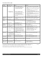
Page 13: ... siphoning properly 3 Improper loading of brew basket 1 Are correct filters being used 2 Refer to dripping step 1 3 Filter and coffee in brew basket 1 Use correct filter 2 Refer to dripping step 1 3 Filter should be centered in brew basket and coffee bed should be level Warmer Station 1 Warmer defective 2 Warmer On Off switch 3 Bad harness 1 Voltage at warmer terminals should be 120V 230V for E mo...

Page 14: ... all electrical connections are tight and isolated MAIN THERMOSTAT 1 Disconnect wires and remove tank and tank lid assembly 2 Remove two rear screws mounting tank to tank lid 3 Remove screws which secure thermostat to tank lid 4 Loosen thumb nut securing capillary bulb 5 Remove grommet from top of tank lid by pressing up with thumb and pulling capillary bulb out through hole 6 Reverse steps 1 5 to...

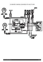
Page 15: ...Auto Series Brewer Manual Page 15 SCHEMATIC WIRING DIAGRAM AT 2W AT 2WE ...

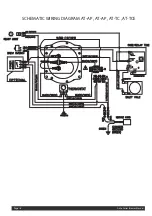
Page 16: ...Auto Series Brewer Manual Page 16 SCHEMATIC WIRING DIAGRAM AT AP AT AP AT TC AT TCE ...

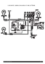
Page 17: ...SCHEMATIC WIRING DIAGRAM AT 3WR AT 3WRE Auto Series Brewer Manual Page 17 ...

Page 18: ...Auto Series Brewer Manual Page 18 SCHEMATIC WIRING DIAGRAM AT 3W AT 3WE ...

Page 19: ......

Page 20: ...everage Dispensers Crathco Cold and Frozen Beverage Dispensers AMW Coffee and Tea Systems Tel 502 425 4776 Fax 502 425 4664 1 800 695 4500 USA Canada only P O Box 35020 Louisville KY 40232 USA www grindmaster com email info grindmaster com Grindmaster Corporation 2007 PRINTED IN USA 0307 Form BW 340 02 Part 73254 ...

Reviews: