ing a fire condition) should be verified
at least once a year as follows:
1. If water must be prevented from flow-
ing beyond the riser, perform the fol-
lowing steps.
a.
Close the Main Control Valve.
b.
Open the Main Drain Valve.
c.
Open the Main Control Valve
one turn beyond the position at
which water just begins to flow
from the Main Drain Valve.
d.
Close the Main Drain Valve.
2. Determine the type of actuation/de-
tection system, and operate the
F470 Valve accordingly.
NOTE
Be prepared to quickly perform
Steps 3, 4, and 5, if water must be
prevented from flowing beyond
the riser.
Wet Pilot Actuation — Open the
Inspector’s Test Connection.
Dry Pilot Actuation — Open the
Inspector’s Test Connection.
Electric Actuation — Test the del-
uge releasing panel (automatic con-
trol unit) in accordance with the
manufacturer’s instructions to ener-
gize the solenoid valve.
3. Verify that the F470 Valve has
tripped, as indicated by the flow of
water into the system.
4. Close the Diaphragm Chamber Sup-
ply Control Valve.
5. Close the system’s Main Control
Valve.
6. Reset the F470 Deluge Valve in ac-
cordance with the Valve Setting Pro-
cedure.
Five Year Internal Valve Inspection
Once every five years during the an-
nual operational test procedure and
prior to the F470 Valve being reset, the
internal parts of the F470 Valve should
be cleaned and then inspected for
wear and damage. Make certain that
the two 1/8 inch (3,2mm) diameter
pressure equalizing vents in the top of
the Clapper are open. Special consid-
eration should be given to the condi-
tion of the Diaphragm and the Clapper
Facing. The Diaphragm and/or Clap-
per Facing should be replaced if there
are any signs of deterioration due to
age or chemicals in the water.
NOTE
If the water supply contains chemi-
cals which tend to attack an EPDM
type rubber or the five year inspection
indicates a build-up of debris within
the valve which could affect its proper
operation, then the frequency of the
internal valve inspection procedure
should be increased as appropriate.
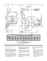
Worn or damaged parts must be re-
placed and the F470 Valve must be
reassembled in accordance with Fig-
ure B. The Cap Screws securing the
Diaphragm and Handhole Covers
should be uniformly tightened using a
cross-draw sequence.
Quarterly Solenoid Valve Test Pro-
cedure For Electric Actuation
Proper operation of the Solenoid Valve
for electric actuation should be verified
at least quarterly as follows:
1. Close the Main Control Valve.
2. Open the Main Drain Valve.
3. Test the automatic control unit (del-
uge releasing panel) in accordance
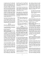
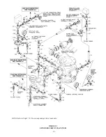
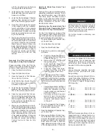
FIGURE G-3
DELUGE VALVE SYSTEM SCHEMATIC
— ELECTRIC ACTUATION—
-13-
OBSOLETE

