with the manufacturer’s instructions
to energize the solenoid valve.
4. Verify that the flow of water from the
Solenoid Valve drain connection in-
creases to a full flow.
5. Verify that the Diaphragm Chamber
pressure has decreased to below
25% of the water supply pressure.
6. Reset the electric detection system
in accordance with the manufac-
turer’s instructions to de-energize
the solenoid valve. Check the Sole-
noid Valve drain for leaks. Any leaks
must be corrected before proceed-
ing to the next step.
7. Slowly open the Main Control Valve.
Close the Main Drain Valve as soon
as water discharges from the drain
connection. Observe the Automatic
Drain Valve for leaks. If there are
leaks, determine/correct the cause
of the leakage problem. If there are
no leaks, the F470 Valve is ready to
be placed in service and the Main
Control Valve must then be fully
opened.
Quarterly Dry Pilot Actuator Test
Procedure For Dry Pilot Actuation
Proper operation of the Dry Pilot Ac-
tuator for dry pilot actuation should be
verified at least quarterly as follows:
1. Close the Main Control Valve.
2. Open the Main Drain Valve.
3. Open the Inspector’s Test Connec-
tion on the Dry Pilot Line.
4. Verify that the flow of water from the
Dry Pilot Actuator drain connection
increases to a full flow.
5. Verify that the Diaphragm Chamber
pressure has decreased to below
25% of the water supply pressure.
6. Close the Inspector’s Test Connec-
tion and allow the dry pilot line pres-
sure to re-establish. Check the Dry
Pilot Actuator drain for leaks. Any
leaks must be corrected before pro-
ceeding to the next step.
7. Slowly open the Main Control Valve.
Close the Main Drain Valve as soon
as water discharges from the drain
connection. Observe the Automatic
Drain Valve for leaks. If there are
leaks, determine/correct the cause
of the leakage problem. If there are
no leaks, the F470 Valve is ready to
be placed in service and the Main
Control Ave must then be fully
opened.
Quarterly Waterflow Alarm Test
Procedure
Testing of the system waterflow alarms
should be performed quarterly. To test
the waterflow alarm, open the Alarm
Test Valve, which will allow a flow of
water to the Pressure Alarm Switch
and/or Water Motor Alarm. Upon satis-
factory completion of the test, close
the Alarm Test Valve.
Quarterly Low Pressure Alarm Test
Procedure And Condensate Drain
Procedure For Dry Pilot Actuation
For Dry Pilot Actuation, testing of the
Low Pressure Alarm Switch and drain-
age of the pilot line condensate should
be performed quarterly as follows.
1. Close the Diaphragm Chamber Sup-
ply Control Valve.
2. Close the Main Control Valve.
3. Open the Main Drain Valve.
4. Drain the dry pilot line condensate
as follows.
a.
Close the Gauge Test Valve lo-
cated below the Dry Pilot Line
Pressure Gauge.
b.
Remove the 1/4" Plug from the
Gauge Test Valve.
c.
Crack Open the Gauge Test
Valve and allow all conden-
sate, if any, to drain out.
d.
Close the Gauge Test Valve,
replace the Plug, and then
open the Gauge Test Valve.
5. Open the Inspector’s Test Connec-
tion, and slowly relieve pneumatic
pressure. Verify that the Low pres-
sure Alarm Switch is operational and
that the low pressure set points are
as follows:
•
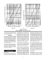
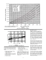
Low pressure alarm setting at
approximately 6 psi (0,4 bar)
below the minimum pilot line
service pressure requirement
shown in Graph C.
•
Fire alarm setting at approxi-
mately 15 psi (1,0 bar) below
the minimum pilot line service
pressure requirement shown
in Graph C.
6. Close the Inspector’s Test Connec-
tion, and allow the Dry Pilot Line to
automatically repressurize.
7. Open the Diaphragm Chamber Sup-
ply Control Valve.
8. Slowly open the Main Control Valve.
Close the Main Drain Valve as soon
as water discharges from the drain
connection. Observe the Automatic
Drain Valve for leaks. If there are
leaks, determine/correct the cause
of the leakage problem. If there are
no leaks, fully open the Main Control
Valve.
WARRANTY
Seller warrants for a period of one year
from the date of shipment (warranty
period) that the products furnished
hereunder will be free from defects in
material and workmanship.
For further details on Warranty, see
Price List.
ORDERING PROCEDURE
All orders for Model F470 Multimatic
Deluge Valves, trim, accessories, and
replacement parts must include the
description and Product Symbol
Number (PSN), where applicable.
Valves:
Unless otherwise specified, the F470
Valves will be provided with ANSI
flange drilling.
Specify: (specify size) Model F470 Ex-
ternal Resetting Multimatic Deluge
Valve with (specify abbreviation — re-
fer to Table A, Page 2) flange drilling,
PSN (specify).
ANSI
4" (100 mm) . . . . . . . . . . . . . . PSN 52-470-1-013
6" (150 mm) . . . . . . . . . . . . . . PSN 52-470-1-015
ISO
4" (100 mm) . . . . . . . . . . . . . . PSN 52-470-4-113
6" (150 mm) . . . . . . . . . . . . . . PSN 52-470-4-115
AS
4" (100 mm) . . . . . . . . . . . . . . PSN 52-470-4-313
6" (150 mm) . . . . . . . . . . . . . . PSN 52-470-4-315
JIS
4" (100 mm) . . . . . . . . . . . . . . PSN 52-470-4-713
6" (150 mm) . . . . . . . . . . . . . . PSN 52-470-4-715
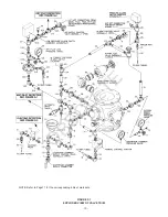
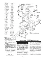
Trim:
Unless otherwise specified, all trim ar-
rangements are provided factory as-
sembled as shown in Figure F-2. Un-
assembled trim packages as shown in
Figure F-1 can be provided on “special
order”. Product Symbol Numbers
(PSN) need not be specified when or-
dering unassembled trim.
-14-
OBSOLETE

