“Standard Order”
Factory Assembled Black Trim:
Specify: Factor y assembled black
(specify type trim) for use with the
Model F470 Multimatic External Re-
setting Deluge Valve, PSN (specify).
Wet Pilot Actuation
Trim . . . . . . . . . . . . . . . . . . . PSN 52-470-1-101
Dry Pilot Actuation
Trim . . . . . . . . . . . . . . . . . . . PSN 52-470-1-102
Electric Actuation
Trim With 24VDC
Solenoid Valve . . . . . . . . . . PSN 52-470-1-103
“Special Order”
Factory Assembled
Galvanized Trim:
Specify: Factory assembled galva-
nized (specify type trim) for use with
the Model F470 Multimatic External
Resetting Deluge Valve, PSN (spec-
ify).
Wet Pilot Actuation
Trim . . . . . . . . . . . . . . . . . . . PSN 52-470-2-101
Dry Pilot Actuation
Trim . . . . . . . . . . . . . . . . . . . PSN 52-470-2-102
Electric Actuation
Trim With 24VDC
Solenoid Valve . . . . . . . . . . PSN 52-470-2-103
“Special Order” Electric Actuation
Trim With Separately Ordered Sole-
noid Valve:
Specify: (Specify Factory assembled
or Unassembled), (specify black or
galvanized) Electric Actuation Trim
With Separately Ordered Solenoid
Valve for use with the Model F470 Mul-
timatic External Resetting Deluge
Valve.
When ordering “Electric Actuation Trim
With Separately Ordered Solenoid
Valve”, refer to Technical Data Sheet
TD119 for information on separately
ordered, UL Listed Solenoid Valves
that may be suitable for use in hazard-
ous locations or that have voltage rat-
ings other than 24VDC.
NOTE
Factory Mutual Approval for electric
actuation of the F470 Valve is contin-
gent on the use of the FM Approved
24VDC Solenoid Valve provided with
the “Standard Order” Electric Actua-
tion Trim, PSN 52-470-1-103 or PSN
52-470-2-103.
Accessories:
Refer to the following Technical Data
Sheets (TD), as applicable.
Pressure Alarm Switch . . . . . . . .
TD213
Low Pressure Alarm Switch . . . .
TD210
Model F324 Air Maintenance
Device . . . . . . . . . . . . . . . . . . .
TD111
Model F326 Air Maintenance
Device . . . . . . . . . . . . . . . . . . .
TD112
Model F328 Nitrogen Maintenance
Device . . . . . . . . . . . . . . . . . . .
TD113
Desiccant Dryer . . . . . . . . . . . . .
TD135
Model F180 or F184
Manual Control Stations . . . . .
TD121
Valve Replacement Parts Kit:
The Valve Replacement Parts Kit con-
tains a Clapper Facing, Diaphragm,
and Handhole Cover Gasket. It is rec-
ommended to have these parts readily
available when servicing the Model
F470 Multimatic Deluge Valve.
Specify: Valve Replacement Parts Kit
for use with (specify size) inch Model
F470 Multimatic External Resetting
Deluge Valve.
4" (100 mm) . . . . . . . . . . . . . . PSN 92-470-1-101
6" (150 mm) . . . . . . . . . . . . . . PSN 92-470-1-102
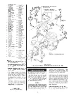
Replacement Valve Parts (Fig. B):
Specify: (description) for use with
(specify size) Model F470 Multimatic
External Resetting Deluge Valve, PSN
(specify).
4 inch (100 mm) Valve
2 - Clapper . . . . . . . . . . . . . . . PSN 92-470-1-006
3 - Clapper Facing . . . . . . . . . PSN 92-470-1-009
4 - Clapper Facing
Retainer . . . . . . . . . . . . PSN 92-470-1-004
5 - Clapper Bolt . . . . . . . . . . . PSN 62-634-1-112
7 - Clapper Latch . . . . . . . . . . PSN 92-470-1-005
8 - O-Ring . . . . . . . . . . . . . . . PSN 62-578-1-306
9 - Reset Bushing . . . . . . . . . PSN 92-470-1-052
10 - O-Ring . . . . . . . . . . . . . . PSN 62-578-1-307
11 - Reset Plunger. . . . . . . . . PSN 92-470-1-053
12 - Reset Knob. . . . . . . . . . . PSN 62-470-1-001
13 - Diaphragm
Cover Bolt . . . . . . . . . . . PSN 62-039-1-207
14 - Diaphragm
Retainer . . . . . . . . . . . . PSN 92-470-1-049
15 - Flange & Push
Rod Assembly . . . . . . . PSN 92-470-1-040
16 - Diaphragm . . . . . . . . . . . PSN 92-470-1-031
17 - Diaphragm
Cover . . . . . . . . . . . . . . PSN 92-470-1-029
20 - Clapper Hinge
Pin . . . . . . . . . . . . . . . . . PSN 92-470-1-038
21 - Latch Hinge Pin . . . . . . . PSN 92-470-1-023
22 - Handhole Cover . . . . . . . PSN 92-470-1-002
23 - Handhole
Cover Gasket . . . . . . . . PSN 92-470-1-008
24 - Handhole
Cover Bolt . . . . . . . . . . . PSN 62-039-1-208
- Flurosilicone
Grease
1.5 grams . . . . . . . . . . . PSN 92-302-1-641
57 grams . . . . . . . . . . . PSN 92-302-1-642
6 inch (150 mm) Valve
2 - Clapper . . . . . . . . . . . . . . . PSN 92-470-1-025
3 - Clapper Facing . . . . . . . . . PSN 92-470-1-032
4 - Clapper Facing
Retainer . . . . . . . . . . . . PSN 92-470-1-026
5 - Clapper Bolt . . . . . . . . . . . PSN 62-634-1-113
7 - Clapper Latch . . . . . . . . . . PSN 92-470-1-030
8 - O-Ring . . . . . . . . . . . . . . . PSN 62-578-1-306
9 - Reset Bushing . . . . . . . . . PSN 92-470-1-052
10 - O-Ring . . . . . . . . . . . . . . PSN 62-578-1-307
11 - Reset Plunger. . . . . . . . . PSN 92-470-1-053
12 - Reset Knob . . . . . . . . . . . PSN 62-470-1-001
13 - Diaphragm
Cover Bolt . . . . . . . . . . . PSN 62-039-1-207
14 - Diaphragm
Retainer . . . . . . . . . . . . . PSN 92-470-1-049
15 - Flange & Push
Rod Assembly . . . . . . . . PSN 92-470-1-040
16 - Diaphragm . . . . . . . . . . . . PSN 92-470-1-031
17 - Diaphragm
Cover . . . . . . . . . . . . . . . PSN 92-470-1-029
20 - Clapper Hinge
Pin . . . . . . . . . . . . . . . . . PSN 92-470-1-039
21 - Latch Hinge Pin . . . . . . . . PSN 92-470-1-023
22 - Handhole Cover . . . . . . . PSN 92-470-1-021
23 - Handhole
Cover Gasket. . . . . . . . . PSN 92-470-1-033
24 - Handhole
Cover Bolt . . . . . . . . . . . PSN 62-634-1-407
- Flurosilicone
Grease
1.5 grams . . . . . . . . . . . . PSN 92-302-1-641
57 grams . . . . . . . . . . . . PSN 92-302-1-642
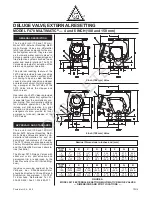
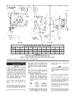
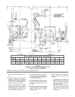
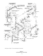
Replacement Trim Parts (Fig. F):
Specify: (description) for use with
Model F470 External Resetting Multi-
matic Deluge Valve, PSN (specify).
1 - 300 lb. Water
Pressure
Gauge . . . . . . . . . . . . . . PSN 92-343-1-005
2 - 1/4" Gauge Test
Valve . . . . . . . . . . . . . . . PSN 46-005-1-002
3 - F180 Manual
Control Station . . . . . . . . PSN 52-289-1-001
4 - 2" Angle Valve . . . . . . . . . . PSN 46-048-1-009
5 - 1/2" Ball Valve . . . . . . . . . . PSN 46-050-1-004
6 - 1/2" Swing
Check Valve. . . . . . . . . . PSN 46-049-1-004
7 - 1/2" Spring
Loaded Check
Valve . . . . . . . . . . . . . . . PSN 92-322-1-002
8 - Priming Supply
Restriction . . . . . . . . . . . PSN 92-020-1-009
9 - 1/2" Y-Strainer . . . . . . . . . . PSN 52-353-1-005
10 - F793 Automat-
ic Drain Valve . . . . . . . . PSN 52-793-1-004
11 - Drip Funnel
Support Plug . . . . . . . . . PSN 92-211-1-005
12 - Drip Funnel
Support . . . . . . . . . . . . . PSN 92-211-1-003
13 - Drip Funnel . . . . . . . . . . . PSN 92-343-1-007
14 - 3/32" Vent
Fitting . . . . . . . . . . . . . . . PSN 92-032-1-002
15 - 1/2" Angle
Valve . . . . . . . . . . . . . . . PSN 46-048-1-004
D1 - B-1 Dry Pilot
Actuator . . . . . . . . . . . . . PSN 52-280-1-001
D2 - 250 lb. Air
Pressure
Gauge . . . . . . . . . . . . . . PSN 92-343-1-012
D3 - 1/4" Gauge
Test Valve . . . . . . . . . . . PSN 46-005-1-002
D4 - 1/2" Globe
Valve . . . . . . . . . . . . . . . PSN 46-047-1-004
D5 - 1/4" Pressure
Relief Valve . . . . . . . . . . PSN 92-343-1-020
E5 - 24VDC Sole-
noid Valve . . . . . . . . . . . PSN 52-287-1-024
WEIGHTS
The following are the nominal weights for
the valves and trim:
4" Model F470 Multimatic
Deluge Valve . . . . . . . . . . . . . .
77 lbs. (35 kg)
6" Model F470 Multimatic
Deluge Valve . . . . . . . . . . . . . . 111 lbs. (49 kg)
Wet Pilot Actuation Trim . . . . . . .
28 lbs. (13 kg)
Dry Pilot Actuation Trim . . . . . . . .
41 lbs. (18 kg)
Electric Actuation Trim
With 24VDC Solenoid Valve . .
33 lbs. (15 kg)
-15-
OBSOLETE

