The Model F470 Multimatic Deluge
Valves are accepted by the City of New
York under MEA 38-92-M.
WARNING
The Model F470 Multimatic Deluge
Valves described herein must be in-
stalled and maintained in compli-
ance with this document, as well as
with the applicable standards of the
National Fire Protection Association,
in addition to the standards of any
other authorities having jurisdiction.
Failure to do so may impair the integ-
rity of these devices.
The owner is responsible for main-
taining their fire protection system
and devices in proper operating con-
dition. The installing contractor or
manufacturer should be contacted
relative to any questions.
TECHNICAL DATA
Deluge Valve:
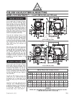
The 4 and 6 inch (100 and 150 mm),
Model F470 External Resetting Multi-
matic Deluge Valves are rated for use
at a maximum service pressure of 175
psi (12,1 bar). The Valve dimensions
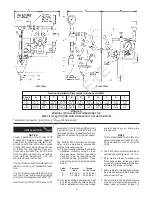
are shown in Figure A, and all of the
por ts are NPT threaded per ANSI
Standard B1.20.1. Flanged inlet and
outlet connections are available drilled
per ANSI, AS, ISO, and JIS specifica-
tion options indicated in Table A. When
the flange drilling is provided to AS,
ISO, or JIS specifications, the label
located on the Handhole Cover indi-
cates the specification to which the
flange drilling has been provided.
The F470 Valve is to be installed verti-
cally, as shown in Figure A. Exterior
surfaces of the F470 Valve are painted
red, and the year of manufacture is
indicated on the Handhole Cover.
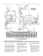
Components of the F470 Valve are
shown in Figure B. The Body, Hand-
hole Cover, and Diaphragm Cover are
ductile iron per ASTM A536 (UNS
F33100). The Handhole Cover Gasket
is neoprene, and the Clapper Facing,
Diaphragm, and O-Rings are EPDM.
The Seat Ring, Clapper, Diaphragm
Retainer, and the Flange of the Flange
& Push Rod Assembly are bronze per
ASTM B62 (UNS C83600).The Clap-
per Latch is aluminum bronze per
ASTM B148 (UNS C956200), the Re-
set Bushing is brass per ASTM B16
(UNS C36000), and the Bearings are
bronze per ASTM B438, Grade 1, Type
II. The Clapper Facing Retainer, Clap-
per Bolt, Reset Plunger, Clapper
Hinge Pin, Latch Hinge Pin, and the
Push Rod of the Flange & Push Rod
Assembly are fabricated from austeni-
tic stainless steel. The Reset Knob is
phenolic, and the Handhole Cover
Bolts, Diaphragm Cover Bolts, and
Pipe Plugs are carbon steel.
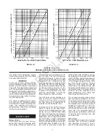
The nominal pressure losses versus
flow are shown in Graphs A-1 and A-2.
The approximate friction losses, based
on the Hazen and Williams formula
and expressed in equivalent length of
Schedule 40 pipe with C = 120, is 12
feet for the 4 inch (100 mm) valve size
and 30 feet for the 6 inch (150 mm)
valve size. The equivalent length of
pipe has been calculated on the basis
of the flow rates typically used with
each size valve.
Valve Trim:
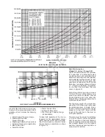
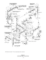
The Wet Pilot Actuation Trim, Dry Pilot
Actuation Trim, or Electric Actuation
Trim illustrated in Figure F-1 form a
part of the laboratory listings and ap-
-3
GRAPHS A-1 and A-2
NOMINAL PRESSURE LOSS VERSUS FLOW
GRAPH A-1
GRAPH A-2
OBSOLETE

