proval of the F470 Valves and are nec-
essary for their proper operation. Each
package of trim includes the following
items:
•
Water Supply Pressure Gauge
•
Diaphragm Chamber
Pressure Gauge
•
Diaphragm Chamber Connections
•
Actuation Devices (as applicable)
•
Main Drain Valve
•
Alarm Test Valve
•
Alarm Control Valve
•
Automatic Drain Valve
•
Dry Pilot Line Pressure Gauge
(as applicable)
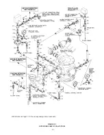
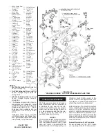
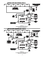
To ease field assembly of the trim ar-
rangements, the appropriate compo-
nents required for Wet Pilot Actuation,
Dry Pilot Actuation, or Electric Actua-
tion are factory assembled as shown
in Figure F-2.
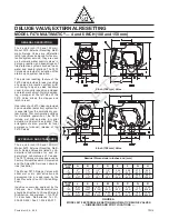
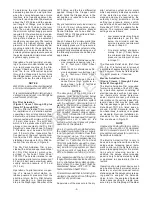
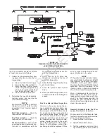
Wet Pilot Actuation
(Figure F-1, Items 1 through 35)
The Wet Pilot Actuation Trim provides
for connection of a detection system
consisting of wet pilot sprinklers (heat
detectors) and manual control stations
interconnected with minimum 1/2 inch
(15 mm) Schedule 40 steel pipe. The
pilot line is connected to the “Wet Pilot
Detection” connection shown in Figure
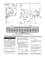
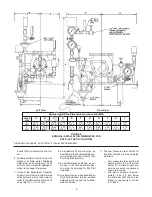
F-1. Nominal installation dimensions
for the Wet Pilot Actuation Trim are
shown in Figure D.
Wet pilot sprinklers are to be minimum
1/2 inch (15 mm) orifice listed or ap-
proved automatic sprinklers. Manual
Control Stations are to be either the
Model F180 or F184 described in Tech-
nical Data Sheet TD121.
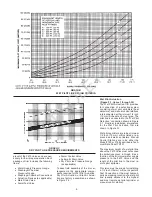
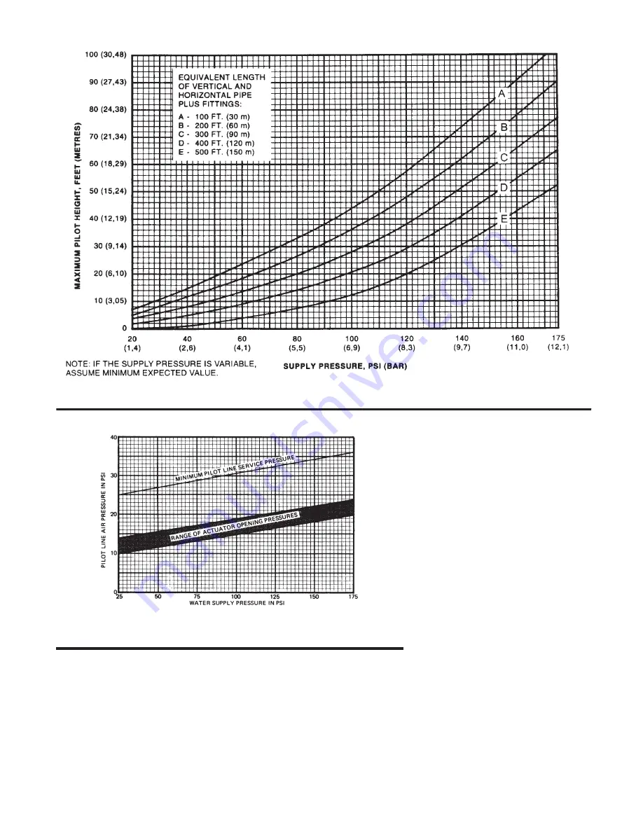
The maximum height of a wet pilot line
above the F470 Valve must not exceed
the limitations given in Graph B as a
function of the minimum water supply
pressure to the F470 Valve and the
length of the pilot line to the most re-
mote pilot sprinkler.
Provision must be made for installing
a 1/2 inch (15mm) orifice, Inspector’s
Test Connection at the most hydrauli-
cally demanding location of a wet pilot
line (usually adjacent to the highest
and most remote wet pilot sprinkler or
manual control station).
-4-
GRAPH B
WET PILOT LINE DESIGN CRITERIA
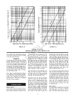
GRAPH C
DRY PILOT LINE PRESSURE REQUIREMENTS
OBSOLETE

