of the F470 Valve, and the force differ-
ential applied through the Clapper
Latch which holds the Clapper down in
the set position is reduced to below the
valve trip point.
NOTE
Consult with the Authority Having
Jurisdiction regarding installation
criteria pertaining to electric actua-
tion circuitry.
OPERATING PRINCIPLES
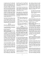
The Model F470 Multimatic Deluge
Valve is a differential latch type valve
which depends upon water pressure in
the Diaphragm Chamber (Ref. Figure
C-1) to hold the Clapper closed
against the water supply pressure. The
nominal trip ratio is 2.5 to 1, i.e., the
F470 Valve operates (opens) when the
pressure in the Diaphragm Chamber is
reduced to approximately 40 percent
of the water supply pressure.
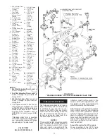
When the F470 Valve is set for service,
the Diaphragm Chamber is pressur-
ized through the trim connections from
the inlet side of the system’s main con-
trol valve, for example an O.S.&Y. gate
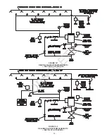
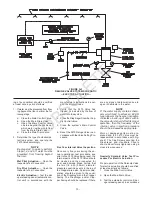
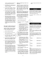
valve or butterfly valve (Ref. Figure G-
1, G-2, or G-3). Opening of an actua-
tion device, for example the solenoid
valve in the Electric Actuation Trim
(Ref. Fig. G-3), releases water from the
Diaphragm Chamber faster than it can
be replenished through the 1/8 inch
(3,2mm) Restriction in the Diaphragm
Chamber Supply Connection. This re-
sults in a rapid pressure drop in the
Diaphragm Chamber and the force dif-
ferential applied through the Clapper
Latch to hold the Clapper down in the
set position is reduced to below the
valve trip point. The water supply pres-
sure then forces the Clapper open per-
mitting water to flow into the system
piping, as well as through the Alarm
Port to actuate the system alarms (Ref.
Figure C-2).
When the system main control valve is
closed to stop waterflow into the sys-
tem, the Clapper will be prevented
from resetting by the Clapper Latch
until the Rest Knob is pushed inward
(Ref. Figure C-3). Pushing the Reset
Knob inward will temporarily reposition
the Clapper Latch away from the wa-
terway and allows the Clapper to drop
into the seated position.
-6-
FIGURE C
MODEL F470 EXTERNAL RESETTING MULTIMATIC DELUGE VALVE
— SET AND OPEN POSITIONS —
— Open Position (Flowing)—
Figure C-2
— Set Position —
Figure C-1
— Open Position (No Flow)—
Figure C-3
OBSOLETE

