INSTALLATION
NOTES
Proper operation of the Model F470
Multimatic Deluge Valves depends
upon their trim being installed in ac-
cordance with the instructions given
in this Technical Data Sheet. Failure
to follow the appropriate trim dia-
gram may prevent the F470 Valve
from functioning properly, as well as
void listings, approvals, and the
manufacturer’s warranties.
The F470 Valve must be installed in a
readily visible and accessible loca-
tion.
The F470 Valve , associated trim, and
wet pilot lines must be maintained at
a minimum temperature of 40°F/4°C.
Heat tracing of the F470 Valve or its
associated trim is not permitted. Heat
tracing can result in the formation of
hardened mineral deposits which are
capable of preventing proper opera-
tion.
The Model F470 Multimatic Deluge
Valve is to be installed in accordance
with the following criteria:
1a. Flange mounting fasteners are to be
tightened uniformly using a cross-
draw sequence. Fastener specifica-
tions are to be as required by the
authority having jurisdiction. Tight-
ening torques are to be as indicated
below.
Valve
Fastener
Torque
Size
Size
Ft. Lbs. (Nm)
4"
5/8" (M16)
40-50 (54-68)
6"
3/4" (M20)
50-65 (68-81)
1b. All nipples, fittings, and devices must
be clean and free of scale and burrs
before installation. Use pipe thread
sealant sparingly on male pipe
threads only.
NOTE
It is recommended that internally
galvanized pipe and cast iron fit-
tings be used for wet or dry pilot
lines.
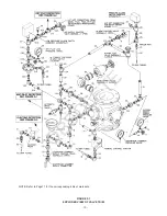
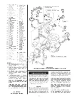
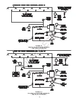
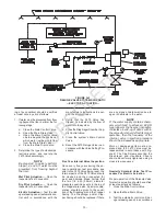
2. The F470 Valve must be trimmed in
accordance with Figures F-1 & F-2.
3. Care must be taken to make sure
that check valves, strainers, globe
valves, etc. are installed with the flow
arrows in the proper direction.
4. Drain tubing to the drip funnel must
be installed with smooth bends that
will not restrict flow.
5. The main drain and drip funnel drain
may be interconnected provided a
check valve is located at least 12
-7-
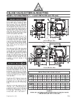
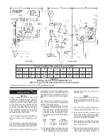
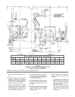
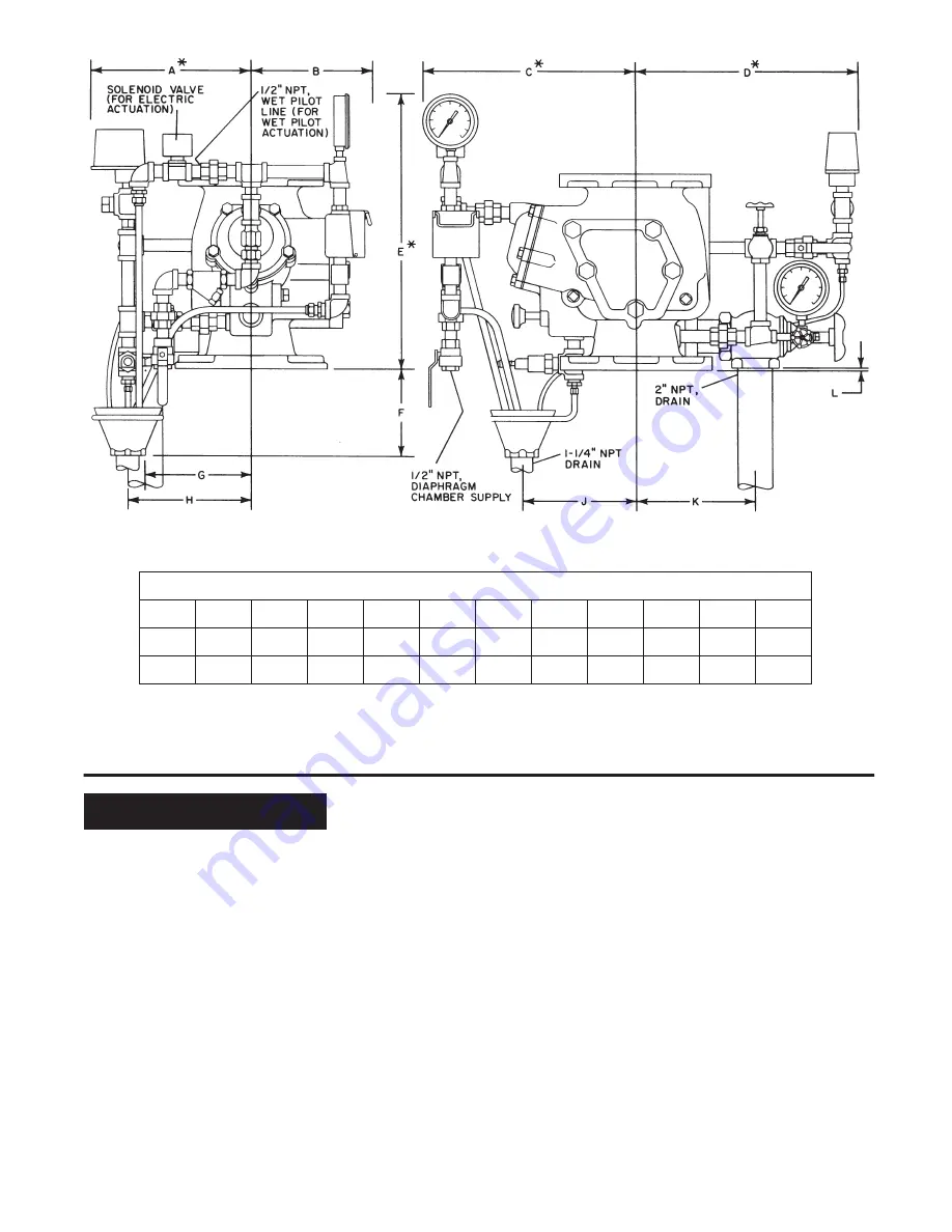
FIGURE D
NOMINAL INSTALLATION DIMENSIONS FOR
WET PILOT ACTUATION TRIM OR ELECTRIC ACTUATION TRIM
Left View
Front View
*
MINIMUM CLEARANCE, ADDITIONAL 2" (50mm) RECOMMENDED
Nominal Installation Dimensions in Inches and (MM)
VALVE
SIZE
4
(100)
6
(150)
A
12.00
(304,8)
12.00
(304,8)
J
7.75
(196,9)
8.56
(217,4)
B
8.69
(220,7)
8.69
(220,7)
K
6.31
(160,3)
6.31
(160,3)
C
14.25
(362,0)
15.12
(384,0)
L
0.25
(6,4)
0.12
(3,0)
D
13.69
(347,7)
14.50
(368,3)
E
19.00
(482,6)
20.00
(508,0)
F
5.44
(138,2)
5.50
(139,7)
G
6.69
(169,9)
7.62
(193,5)
H
8.75
(222,3)
8.88
(225,6)
OBSOLETE

