inches (300 mm) below the drip fun-
nel.
6. Suitable provision must be made for
disposal of drain water. Drainage
water must be directed such that it
will not cause accidental damage to
property or danger to persons.
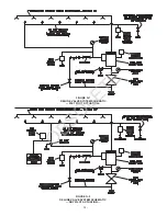
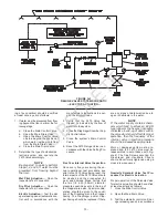
7. Connect the Diaphragm Chamber
Supply Control Valve to the inlet side
of the system’s main control valve in
order to facilitate setting of the F470
Valve (Ref. G-1, G-2, or G-3).
8. An Inspector’s Test Connection, as
described in the Technical Data sec-
tion, must be provided for Wet or Dry
Pilot Actuation systems.
9. An Air Maintenance Device, as de-
scribed in the Technical Data Sec-
tion, must be provided for Dry Pilot
Actuation.
10. A desiccant dryer, when specified for
Dry Pilot Actuation, is to be installed
between a drip leg and the Air Main-
tenance Device.
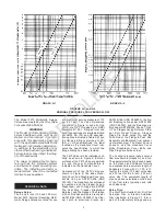
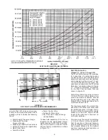
11. The Low Pressure Alarm Switch for
Dry Pilot Actuation is to be adjusted
as follows:
•
Low pressure alarm setting at
approximately 6 psi (0,4 bar)
below the minimum pilot line
service pressure requirement
shown in Graph C.
•
Fire alarm setting at approxi-
mately 15 psi (1,0 bar) below
the minimum pilot line service
pressure requirement shown
in Graph C.
-8-
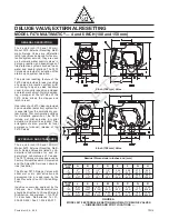
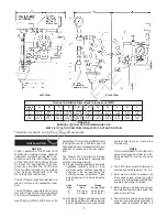
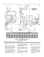
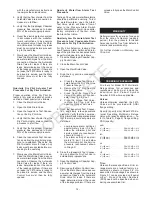
FIGURE E
NOMINAL INSTALLATION DIMENSIONS FOR
DRY PILOT ACTUATION TRIM
Left View
Front View
*
MINIMUM CLEARANCE, ADDITIONAL 2" (50mm) RECOMMENDED
Nominal Installation Dimensions in Inches and (MM)
VALVE
SIZE
4
(100)
6
(150)
A
12.00
(304,8)
12.00
(304,8)
J
7.75
(196,9)
8.56
(217,4)
B
8.69
(220,7)
8.69
(220,7)
K
6.31
(160,3)
6.31
(160,3)
C
14.56
(369,8)
15.44
(392,2)
L
0.25
(6,4)
0.12
(3,0)
D
13.69
(347,7)
14.50
(368,3)
E
30.12
(765,0)
31.12
(790,4)
F
5.44
(138,2)
5.50
(139,7)
G
6.69
(169,9)
7.62
(193,5)
H
8.75
(222,3)
8.88
(225,6)
OBSOLETE

