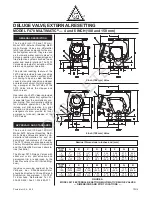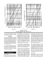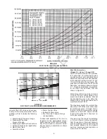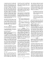
12. Unused pressure alarm switch con-
nections must be plugged.
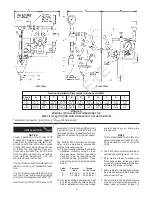
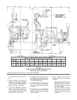
13. The Pressure Relief Valve provided
with the Dry Pilot Actuation Trim is
factory set to relieve at a pressure of
approximately 45 psi (3,1 bar),
which can typically be used for a
maximum normal dry pilot actuation
system pressure of 40 psi (2,8 bar).
The Pressure Relief Valve may be
reset; however, it must be be reset to
relieve at a pressure which is in ac-
cordance with the requirements of
the authority having jurisdiction.
To reset the Pressure Relief Valve,
first loosen the jam nut and then
adjust the cap accordingly — clock-
wise for a higher pressure setting or
counterclockwise for a lower pres-
sure setting. After verifying the de-
sired pressure setting, tighten the
jam nut.
14. Conduit and electrical connections
are to be made in accordance with
the requirements of the authority
having jurisdiction and/or the Na-
tional Electric Code.
VALVE SETTING PROCEDURE
Steps 1 through 12 are to be per-
formed when initially setting the Model
F470 Multimatic Deluge Valve; after an
operational test of the fire protection
system; or, after system operation due
to a fire.
1. Close the Diaphragm Chamber Sup-
ply Control Valve.
2. Close the Main Control Valve, and if
the system is equipped with Dry Pilot
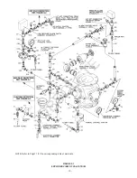
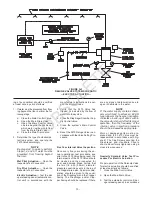
Actuation, close the Air Supply Con-
trol Valve (Ref. Figure F).
3. Open the Main Drain Valve and all
auxiliary drains in the system. Close
the auxiliary drain valves after water
ceases to discharge. Leave the Main
Drain Valve open.
4. Depress the plunger of the Automat-
ic Drain Valve to verify that it is open
and that the F470 Valve is com-
pletely drained.
5. Push the Reset Knob inward to allow
the Clapper to reseat.
Under normal circumstances, the
reseating of the Clapper can be
heard; however, during an annual
operation test procedure, for exam-
ple, due to minimal flow through a
partially opened main control valve,
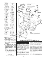
the Clapper may not latch open as
shown in Figure C-3. In which case
the reseating sound of the Clapper
will not be heard.
Also under normal circumstances,
water pressure in the riser will have
exerted sufficient force on the Dia-
phragm so as to have emptied most
of the water from the Diaphragm
Chamber which, in turn, will ease
the pushing of the Reset Knob by
eliminating the resistive force pro-
duced by a water filled Diaphragm
Chamber. Therefore, should water
remain in the Diaphragm Chamber,
the Reset Plunger will need to be
depressed with added force to push
the remaining water out of the Dia-
phragm Chamber and through an
open actuation device (e.g., a Dry
Pilot Actuator or Solenoid Valve).
NOTE
If the Reset Knob can not be de-
pressed sufficiently to allow the
Clapper to reseat, operate (open)
the Manual Control Station and
then once again push the Reset
Knob with sufficient force to push
the water out of the Diaphragm
Chamber through the Manual
Control Station drain.
6. Clean the Strainer in the Diaphragm
Chamber Supply connection by re-
moving the clean-out plug and
strainer basket. The Strainer may be
flushed out by momentarily opening
the Diaphragm Chamber Supply
Control Valve.
7. Open the Alarm Control Valve (Fig.
F), if it was closed to silence local
alarms.
It is recommended that the Alarm
Control Valve be wire sealed in the
open position with a No. 16 twisted
wire, the ends of which are secured
by a lead seal. The wire seal should
be looped through the hole in the
handle and tightly twisted around the
pipe nipple adjacent to the handle.
8. Reset the actuation system.
Manual Actuation — Push the oper-
ating lever up; however, do not close
the hinged cover at this time.
Wet Pilot Actuation — Replace op-
erated pilot sprinklers and/or reset
the manual control stations.
Dry Pilot Actuation — Replace oper-
ated pilot sprinklers and/or reset the
manual control stations. Re-estab-
lish dry pilot pneumatic pressure.
Electric Actuation — Reset the elec-
tric detection system in accordance
with the manufacturer’s instructions
to de-energize the solenoid valve.
NOTE
In order to prevent the possibility
of a subsequent operation of an
overheated solder type pilot sprin-
kler, any solder type pilot sprin-
klers which were possibly exposed
to a temperature greater than
their maximum rated ambient
must be replaced.
9. Open the Diaphragm Chamber Sup-
ply Control Valve and allow time for
full pressure to build up in the Dia-
phragm Chamber.
10. Operate (open) the Manual Control
Station to vent trapped air from the
Diaphragm Chamber. If necessary,
first open the hinged cover, and then
fully pull down on the operating lever.
SLOWLY close the operating lever,
by pushing it up, after aerated water
ceases to discharge from the Man-
ual Control Station drain tubing.
Close the hinged cover and insert a
new break rod in the small hole
through the top of the enclosing
box.
If wet pilot actuation is being used,
crack open the Inspector’s Test Con-
nection and any other vent valves, to
relieve trapped air. After the dis-
charge of air has stopped, close the
vent valves and the Inspector’s Test
Connection.
11. Inspect drain connections from the
Manual Control Station, Solenoid
Valve, Dry Pilot Actuator, and Alarm
Devices, as applicable. Any leaks
must be corrected before proceed-
ing to the next step.
12. Slowly open the Main Control Valve.
Close the Main Drain Valve as soon
as water discharges from the drain
connection. Observe the Automatic
Drain Valve for leaks. If there are
leaks, determine/correct the cause
of the leakage problem. If there are
no leaks, the F470 Valve is ready to
be placed in service and the Main
Control Ave must then be fully
opened.
NOTE
After setting a fire protection system,
notify the proper authorities and ad-
vise those responsible for monitoring
proprietary and/or central station
alarms.
-9-
OBSOLETE

