background image

G-SWS

Assembly and Operating Manual

6 Assembly

4

Depending on the size one (SWS050 to 080) or two (SWS100 to 250) fitting bores according to 

ISO 9409 are available on the robots or grippers side. 

CAUTION! Risk of pinching the fingers when closing the SWS

When assembling, the upper and lower assemblies do not have to be inserted 

into each other as far as they will go. By turning the semi-cylindrical bolt, the 

lower assembly is pulled around the locking stroke (see technical description 

„VH“).

The upper assembly of the SWS Connector is mounted on the robot flange, the manipulator or 

similar actuators. It can be centered with the help of a centering disc. The angular orientation is 

determined by means of a fitting bore. The lower assembly is mounted on grippers, measuring 

instruments or other tools. If the SWS Connector can not be installed directly, adapter flanges 

must be used. Use screws according to DIN 912. For the sizes 50, 63 and 80, screws according to 

DIN 7984 are to be used on the gripper side. The screw-in depth of the screws must be observed. 

We recommend the use of a "medium-tight" screw lock.

Optionally, the SWS can be provided with a MEK Energy Coupling. To mount the MEK the "E" 

option must be specified when ordering the SWS. The MEK is available in different versions. The 

MEK enables the simultaneous coupling of electrical and pneumatic lines when opening or closing 

the SWS. The MEK is mounted with two cylinder screws to the upper and lower assemblies. For 

further installation instructions, please refer to the assembly and operating instructions of the MEK.

CAUTION! 

Perform assembly work only when the power supply is switched off!
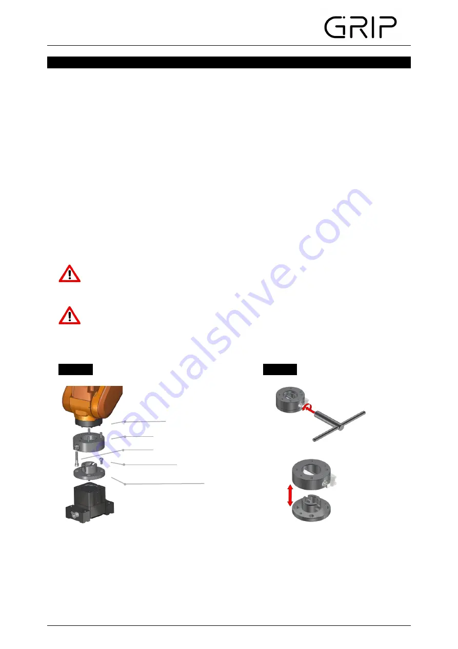
Image 1

Image 2

Robot flange

Upper assembly

ISO 4762

DIN 7984/ ISO 4762

Lower assembly

(MGW050-125 and SWS160-250)

Summary of Contents for G-SWS

Page 1: ... best regards Your GRIP GmbH GRIP GmbH Handhabungstechnik Alter Hellweg 70 Tel 49 231 96450 01 info grip gmbh com 44379 Dortmund Germany Fax 49 231 96450 50 www grip gmbh com SWS Connector 1 3 4 5 8 9 10 8 1 Spare and wear parts Assembly Maintenance and care 7 1 Disassembly 6 Exploded view EC Declaration of incorporation 8 7 7 2 Torque specifications 1 2 Contents 2 2 Intended use Operation Safety ...

Page 2: ... that irreparable damages to the tool or injury to the operator are caused by the unit falling down This symbol indicates possible hazards to persons or the SWS Connector The SWS Connector has been designed as an interface between special solutions and automation e g gripper Furthermore the SWS can also be used as an interface between handling device and tool In dynamic applications it can only be...

Page 3: ...onths from the ex works delivery date under observance the mandatory maintenance and lubrication intervals and the given operating conditions Generally parts touching the work piece and wear parts are not part of the warranty Wear parts are listed in chapter 8 1 The unit is considered to be defective if its basic function Lock is no longer functioning SWS as painted in Image 6 depending on the ord...

Page 4: ...ts or other tools If the SWS Connector can not be installed directly adapter flanges must be used Use screws according to DIN 912 For the sizes 50 63 and 80 screws according to DIN 7984 are to be used on the gripper side The screw in depth of the screws must be observed We recommend the use of a medium tight screw lock Optionally the SWS can be provided with a MEK Energy Coupling To mount the MEK ...

Page 5: ... in image 3 The use of a centering disc ensures that the upper assembly and or lower assembly of the Connector are properly centered Installation on both the upper assembly and lower assembly is possible as shown in image 4 Image 3 Image 4 The SWS is virtually maintenance free Check the semi cylindrical bolt in regular intervals for correct function Keep the mating surface and the moving parts cle...

Page 6: ...1 Screw VS2 optional 11 Anti rotation protection EG SWS VS2 1 Pos Description Order No Quantity 2 Semi cylindrical bolt Quantity 1 10 Square Socket Key ZG VKS SW 1 EG SWS HB 1 8 size 050 125 size 125 250 Description Upper assembly Semi cylindrical bolt Setscrew Pos Description 1 Upper assembly 2 Semi cylindrical bolt 1 3 Setscrew 1 7 Flap VS2 1 4 Index pin 1 5 Housing VS2 1 8 Cylinder bolt VS2 1 9...

Page 7: ...G SWS Assembly and Operating Manual 9 Exploded view 7 Image 5 Image 6 Upper assembly Lower assembly ...

Page 8: ... time of the declaration He further states that the following essential requirements of the Machinery Directive 2006 42 EC were applied and observed annex I numerics 1 1 2 1 1 3 1 1 5 1 3 2 1 7 4 He further states that the specific technical documentation has been drawn up in accordance with annex VII Part B The following harmonized standard has been applied Safety of Machinery Basic concepts gene...

Reviews: