


MEK-PM
GRIP GmbH Handhabungstechnik Tel.: 0231/96450-01 www.grip-gmbh.com info@grip-gmbh.com
MBA-MEK-PM-EN
07/2019
Assembly and Operating
Manual
3
6 Assembly
1. To connect the pneumatic feedthroughs, the customer-side pneumatic screw connections
(M5), must be connected to the threaded bores at the side of the MEK.
2. To connect the electrical feedthroughs, unscrew the electric covers (item 3).
3. The complete insulation elements (items 11 and 12) can be removed to solder the
connections. Attention! The solder contacts are mounted in a floating manner, their
movement margin may not be restricted after soldering (for example by cables which are
too thick or by shrink tubing).
4. Once the connections have been completed, the insulating body must be pushed back into
the housing as far as it will go (item 1 or 2).
5. To adjust the upper and lower parts, the upper part (item 1 reference part) has to
assembled completely. Subsequently, the lower parts (item 2) are mechanically joined and
the insulating body of the lower part is aligned by simple plugging onto the contacts of the
upper part. In this case, only one position is possible (polarity-proof insulating body).
6. If several lower parts are used, this process is repeated accordingly, the upper part is always
the reference piece.
7. Subsequently the o-rings (pos. 8) and the distance bushings (pos. 5) must be pushed in and
covers (pos. 3) must be mounted.
1.
The electrical plug (item 8) belongs to the MEK upper part, the electrical socket (item 7)
belongs to the MEK lower part.
7 Maintenance and care
The O-rings (item 6 and 8) are slightly to grease.
7.1 Disassembly of the MEK
(See Image. 1, Image. 2 and Image. 3)
1. Remove all compressed air lines
2. Remove the mounting screws (items 9, 10 and 14)
3. Remove the electric covers (Pos.3)
4. Remove the distance bushings and the o-rings (item 5 and 8).
5. Thoroughly clean all parts and check for wear and defects
6. Grease all sealing surfaces
7. Replace all seals
Reassemble in reverse order
.
7.2 Bolting torque
M2,5
–
0,5 Nm; M3
–
1,0 Nm; M4
–
2,0 Nm; M5
–
4,0 Nm
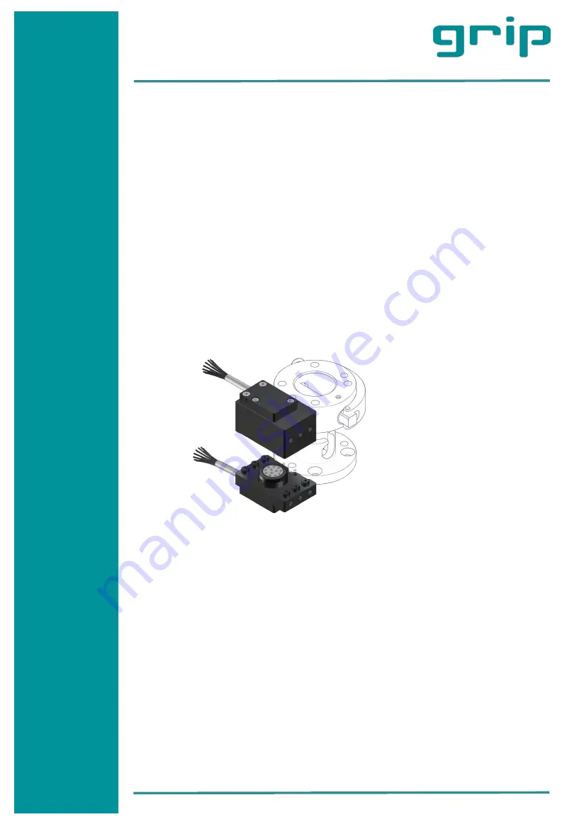
Image. 1


