background image

Italiano

9

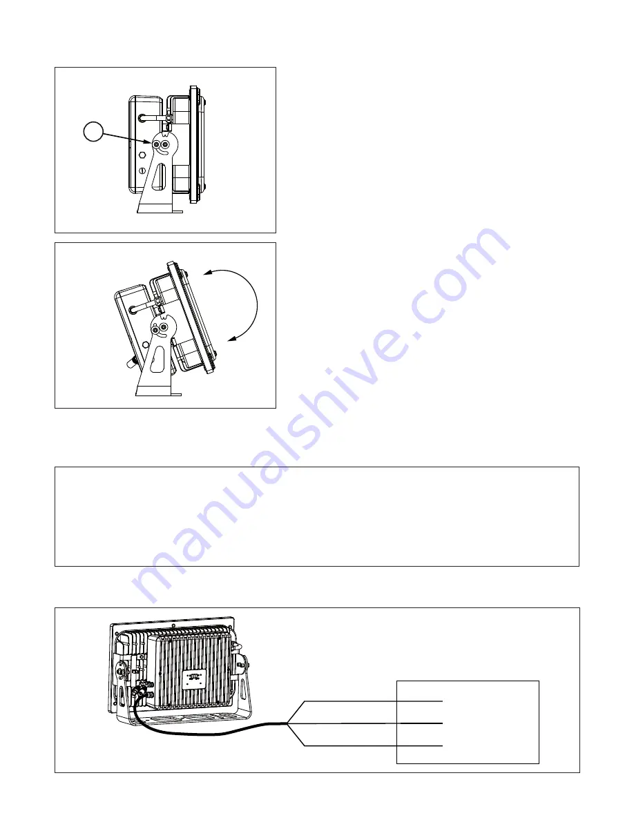
6.3 Orientamento del fascio di luce

A.

Allentate le viti laterali 

“6”

.

B.

Ruotare il corpo nella direzione desiderata e serrate le viti.

6.4 Collegamento della tensione di alimentazione

Il proiettore può funzionare con tensioni da 90 a 250Vac e con frequenze di 50 e 60Hz.

Collegate il cavo di alimentazione posteriore secondo lo schema riportato nella figura seguente.

Fase

Terra

Neutro

Marrone

Giallo Verde

Blu

Tensione di alimentazione

Attenzione!

• Prima di collegare l’apparecchio assicuratevi che la fornitura elettrica corrisponda a quelle ammesse.

• Non installate mai l’apparecchio senza la connessione di terra.

• E’ consigliato l’uso di un interruttore magnetotermico/differenziale sulla linea di alimentazione, come prescritto

dalle norme in vigore.

• Non alimentate il proiettore attraverso unità di potenza dimmer.

• Le operazioni di cablaggio e collegamento devono essere eseguite da personale qualificato.

6

Summary of Contents for AL2925

Page 1: ...POWERSHINE S ULTRA SPOT AL2925 Manuale di istruzioni Instructions manual ...

Page 2: ... del proiettore 13 7 2 1 Funzione dei pulsanti 13 8 0 Funzionamento in modalità DMX 14 8 1 Configurazione del numero dei canali DMX 14 8 2 Impostazione indirizzo DMX 14 8 3 Funzioni DMX 14 8 3 1 Funzioni DMX con modalità 4 canali 14 8 3 2 Funzioni DMX con modalità 5 canali 14 8 3 3 Funzioni DMX con modalità 6 canali 15 9 0 Funzionamento in modalità MASTER SLAVE e AUTOMATICO 15 9 1 Configurazione A...

Page 3: ...de 29 7 2 Unit control panel 29 7 2 1 Reading the display and using controls 29 8 0 DMX function mode 30 8 1 Setting DMX channels 30 8 2 Setting DMX address 30 8 3 DMX functions 30 8 3 1 DMX functions with DMX MODE 4 channels 30 8 3 2 DMX functions with DMX MODE 5 channels 30 8 3 3 DMX functions with DMX MODE 6 channels 31 9 0 Master Slave and Automatic function 31 9 1 AUTOMATIC configuration 31 9...

Page 4: ...ella classificazione di apparecchio con grado di protezione IP66 1 2 Condizioni di garanzia Ogni articolo prodotto dalla ditta italiana GRIVEN Srl è stato assemblato e costruito in conformità alle vigenti norme e normative CE Ogni singolo prodotto e componente sono stati testati prima dell assemblaggio finale ed ogni prodotto è sot toposto ad un controllo di qualità interno prima di essere spedito...

Page 5: ...a lenti C Scheda led D Corpo proiettore E Scatola alimentatore F Coperchio posteriore G Forcella 2 0 Dimensioni 240mm 9 4 240mm 9 4 363mm 14 3 548mm 21 6 R300m m 11 8 Ø12 50mm 0 5 Ø12 50mm 0 5 130mm 5 1 218mm 8 6 336mm 13 2 3 0 Componenti del proiettore A B D E F G C ...

Page 6: ... di questo manuale in modo da apprendere tutte le informazioni relative al proiettore A Aprite l imballo e verificate il contenuto B Installate il proiettore C Collegate il segnale DMX mediante i cavi 1 a lato della sca tola posteriore dell apparecchiatura D Alimentate il proiettore utilizzando il cavo di alimentazione 2 a lato della scatola posteriore dell apparecchiatura E Impostate l indirizzo ...

Page 7: ...re usata più di una volta perciò si raccomanda vivamente l uso di uno dei nostri flight case per trasportare l apparecchiatura Attenzione La responsabilità di Griven S r l cessa all atto della consegna del materiale al vettore reclami per eventuali danni dovuti al trasporto dovranno essere indirizzati direttamente al corriere Si accettano reclami entro e non oltre i 7 giorni dal ricevimento della ...

Page 8: ... 6 2 Cavo di sicurezza Se agganciate POWERSHINE S ULTRA SPOT ad un americana o struttura di supporto dovete installare un cavo di sicurezza che possa sostenere almeno 10 volte il peso dell apparecchiatura come prescritto dalla normativa vigente Agganciate la catena o il cavo di sicurezza 5 facendola passare all interno delle alette del dissipatore come indicato in figura 5 Attenzione Verificate ch...

Page 9: ...lla figura seguente Fase Terra Neutro Marrone Giallo Verde Blu Tensione di alimentazione Attenzione Prima di collegare l apparecchio assicuratevi che la fornitura elettrica corrisponda a quelle ammesse Non installate mai l apparecchio senza la connessione di terra E consigliato l uso di un interruttore magnetotermico differenziale sulla linea di alimentazione come prescritto dalle norme in vigore ...

Page 10: ...e al suo interno un pezzo di guaina termoretraibile e 4 giunti testa testa B Infilate la guaina 7 sul cavo di alimentazione 8 a lato della scatola posteriore dell apparecchiatura C Effettuate la connessione alla rete utilizzando i giunti testa testa 9 pressandoli con uno strumento adeguato 10 D Scaldate la guaina utilizzando un riscaldatore per termore traibili 11 fino al completo restringimento L...

Page 11: ...ite il sacchetto con etichetta DMX Troverete al suo interno 2 pezzI di guaina termoretraibile e 7 giunti testa testa B Infilate la guaina 12 sul cavo di segnale DMX 13 a lato della scatola posteriore dell apparecchiatura C Effettuate la connessione alla rete utilizzando i giunti testa testa 14 pressandoli con uno strumento adeguato 15 14 15 12 13 Attenzione La schermatura ed i conduttori non devon...

Page 12: ... terminazione con resistenza da 120 Ω collegata tra DATA e DATA come indicato di seguito Eseguite le fasi A e B come descritto precedentemente C Collegate la resistenza da 120 Ω 17 tra DATA e DATA e pressate i giunti con uno strumento adeguato D Scaldate la guaina 18 utilizzando un riscaldatore per termo retraibili 19 fino al completo restringimento e poi pressate la parte finale della guaina con ...

Page 13: ...la funzione per tornare al funzionamneto DMX 7 2 Pannello di controllo del proiettore Il display del proiettore è programmato per spegnersi automaticamente dopo 20 secondi di inattività Per atti varlo basta premere un qualsiasi tasto Il led DMX emette luce continua quando il proiettore ri ceve un segnale DMX mentre lampeggia quando non riceve alcun segnale Il led SET è attivo quando viene cambiato...

Page 14: ...io dell indirizzo e tramite i pulsanti UP e DOWN selezionate il valore desiderato Premete ENTER per confermare 8 3 Funzioni DMX 8 3 1 Funzioni DMX con modalità 4 canali 8 3 2 Funzioni DMX con modalità 5 canali Canale Funzione Valore Descrizione 1 Rosso 0 255 Controllo proporzionale 0 100 del colore Rosso 2 Verde 0 255 Controllo proporzionale 0 100 del colore Verde 3 Blu 0 255 Controllo proporziona...

Page 15: ... Premete ENTER per con fermare Mediante questa opzione è possibile selezionare i tempi di durata delle scene colore in secondi Selezionate il valore desiderato tra 5 10 20 e 40 premendo il tasto ENTER Ora premendo i tasti UP o DOWN è possibile scorrere gli 8 programmi preimpostati P1 P8 Una volta posizionati sul programma desiderato premete ENTER Selezionate ON o OFF per attivare o disatti vare il...

Page 16: ... COLORI FISSI Premete ENTER per confermare Ora premendo i tasti UP o DOWN è possibile scorrere i colori 1 Rosso RED 2 Verde GRE 3 Blu BLU 4 Bianco UHT Una volta posizionati sul colore desiderato premete ENTER Selezionate ON o OFF per attivare o disattivare il co lore Premete ENTER per confermare Ora il proiettore è in modalità COLORI FISSI e sul diplay rimarrà visualizzato COL Per uscire dalla mod...

Page 17: ...luminosità massima visualizzazione costruttore Viene visualizzato il nome del costruttore dell apparecchio Griven descrizione modello Viene visualizzato il modello dell apparecchio Powershine MK2 descrizione versione software Viene visualizzato la versione del firmware in uso sull apparecchio PowerShine MK2 v x xx visualizzazione temperatura Viene visualizzato il valore della temperatura di funzio...

Page 18: ...tura del corpo proiettore o delle scatole posteriori le viti del supporto vetro devono essere serrate con una coppia di 4Nm mentre quelle delle scatole posteriori con una coppia di 2 5Nm Tutti i componenti del proiettore sono disponibili come parti di ricambio presso i rivenditori Griven Le viste esplose lo schema elettrico e il diagramma elettronico sono disponibili su richiesta Per facilitare il...

Page 19: ...gamento dati non terminato Inserire una spina di termine nel jack di uscita dell ultima apparecchiatura del collegamento Scorretta assegnazione di indirizzi dei proiettori Controllare gli indirizzi delle apparecchiature e le impostazioni del protocollo Una delle apparecchiature è difettosa e disturba la trasmissione di dati nel collegamento Cortocircuitare un apparecchiatura alla volta fino a quan...

Page 20: ... product manufactured by GRIVEN srl of Italy is assembled and built in accordance to current CE con formity rules and regulations Every single product and component has been tested before the final assembling and all products must pass the in house quality control before they are shipped GRIVEN srl of Italy guarantees the good quality and manufacture of the products and undertakes to repair or sup...

Page 21: ...er B Lenses cover C Led PCB D Fixture body E Power supply box F Rear cover G Bracket 2 0 Size 240mm 9 4 240mm 9 4 363mm 14 3 548mm 21 6 R300m m 11 8 Ø12 50mm 0 5 Ø12 50mm 0 5 130mm 5 1 218mm 8 6 336mm 13 2 3 0 Components of the unit A B D E F G C ...

Page 22: ...rs in this manual are therefore supposed to be read in order to learn all pieces of necessary information relevant to the unit A Open the box and check the content B Install the unit C Connect the DMX signal by using the cable 1 in the side of the power supply box D Power up the unit by using the cable 2 in the side of the power supply box E Adjust the DMX address and the operating mode by using t...

Page 23: ...refore it is recommended to use one of our flight cases to transport the unit Warning Griven S r l liability will cease upon consignment of goods to the forwarder claims for damage due to trans port must be addressed directly to the forwarder Griven S r l will accept claims for broken or missing goods only within seven days of receipt of the goods Returns of equipment will not be accepted without ...

Page 24: ...les in the bracket as shown in the picture 6 2 Safety chain If hooking POWERSHINE S ULTRA SPOT up to a truss or a supporting structure a safety chain must be installed This safety chain must be able to bear at least 10 times the weight of the unit as prescribed by in force rules Hook the safety chain 5 as shown in the picture 5 Warning Check that the fixing hook is not damaged and is able to bear ...

Page 25: ... the rear boxl of the fixture and connect as shown below Live Ground Neutral Brown Yellow Green Blue Main supply Warning Before connecting the unit verify that power supplies features are compatible with the unit features The unit must never be installed if not grounded electrically It is suggested to use a magnetothermic switch along the power supply line as prescribed by in force rules The unit ...

Page 26: ...will find inside a piece of heat shrink tube and 4 butt connectors B Insert the tube 7 onto the power supply cable 8 on the side of the rear box of the unit C Make the connection to the network by using the butt connectors 9 pressing them with a proper tool 10 D Warm up the tube by using a heater for heat shrink tubes 11 till the complete shrinkage The connection so obtained features an IP67 prote...

Page 27: ...these instructions A Open the bag with label DMX You will find inside two pieces of heat shrink tube and 7 butt connectors B Insert the tube 12 onto the dmx cable 13 on the side of the rear box of the unit C Make the connection to the network by using the butt connectors 14 pressing them with a proper tool 15 14 15 12 13 Warning All data wires must be isolated one from another and from the shield ...

Page 28: ...rt a 120 Ω terminal resistor connected between DATA and DATA as shown and following Execute stages A and B as previously described C Connect the 120 Ω resistor 17 between DATA and DATA and press the butt connectors by a proper tool D Heat the tube 18 by using a heater for heat shrink tubes 19 till the complete shrinkage and then press the final end of the tube with a pincer 20 in order to seal the...

Page 29: ...s function to go back to the DMX mode 7 2 Unit control panel The display of the unit is programmed to turn off automatically after 20 seconds of non working To activate it just press any key In the presence of the DMX signal the red led will steadily be on while in the absence of DMX signal the led will flash The green led is on during DMX address is setting menu setting 7 2 1 Reading the display ...

Page 30: ... ton to activate the function Then select the desired value between 1 and 512 through the UP and DOWN keys Press ENTER to confirm 8 3 DMX functions 8 3 1 DMX functions with DMX MODE 4 channels 8 3 2 DMX functions with DMX MODE 5 channels Channel Function Value Description 1 Red 0 255 Proportional control 0 100 of the Red color 2 Green 0 255 Proportional control 0 100 of the Green color 3 Blue 0 25...

Page 31: ...irm Through the UP and DOWN keys select the length of time desired 5 10 20 40 seconds and press ENTER to confirm Now through the UP and DOWN keys it is possible to scroll the 8 preset programmes P1 P8 Once positioned onto the desired programme press ENTER to confirm By the keys UP and DOWN select ON or OFF It is possible to activate or disactivate the programme Press ENTER to confirm MASTER SLAVE ...

Page 32: ...nfirm Now through the UP and DOWN keys it is possible scroll the colours 1 Red RED 2 Green GRE 3 Blue BLU 4 White UHT Once positioned onto the desired colour press ENTER to confirm By the keys UP and DOWN select ON or OFF It is possible to activate or disactivate the colours Press ENTER to confirm Now the unit is in FIXED COLOURS mode and the diplay will keep reading COL To exit from the FIXED COL...

Page 33: ...he identification happens by swit ching on at full intensity all the LEDs Manufacturer The name of the manufacturer Griven is displayed Model description The projector model Powershine MK2 is displayed Software version description The version of the firmware in use on the projector Powershine MK2 v x xx is displayed Temperature The LEDs operating temperature value is displayed An internal temperat...

Page 34: ...he rear boxes the screws of the glass holder must be tightened by a 4 Nm tightening torque while the screws of the rear boxes by a 2 5Nm tightening torque All components of the unit are available as spare parts at Griven dealers Exploded views wiring diagrams electronic layouts and advertising brochures are available on request To make the job of assistance centres easier specify serial number and...

Page 35: ...nfinished data connection Insert a terminal plug in the output jack of the last unit of the connection Incorrect address assignment to the units Check the addresses of the units and the protocol settings One of the unit is faulty and it is affecting the data transmission along the connection Short circuit units singularly one by one since regular working is restored It has been set up an oper atin...

Page 36: ...a Bulgaria 16 46042 CASTEL GOFFREDO MN Italy Telefono 0376 779483 Fax 0376 779682 0376 779552 http www griven com e mail griven griven com http www griven it e mail griven griven it User s manual rel 1 00 ...

Reviews: