


0
0
7.
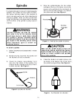
Secure the center bolt.
5.
4.
8.
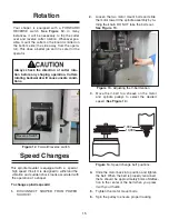
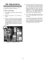
Figure 9.
Adjusting to ensure flatness.
6.
Adjust the wing up or down at the last bolt
(
Figure 9
). If necessary, use a clamp and
some wood blocks to make the two surfaces
flush. Tighten the final bolt when the two sur-
faces are flush
.
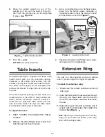
Figure
Installing extension wing.
Make sure the wing edge is flush at the first
two bolts and that the bolts are tight.
Note:
The end of the wing at the last bolt
may not be flush with the surface of the table.
Don’t be alarmed.
13
Inspect your results with a good-quality
straightedge.
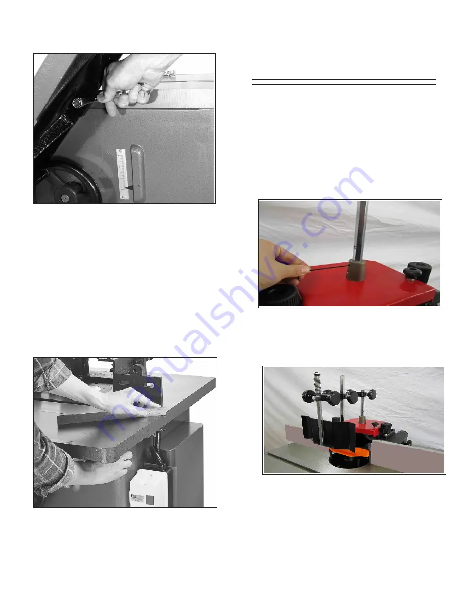
Fence Assembly
To install the fence assembly:
1.
KEEP SHAPER DISCONNECTED FROM
POWER!
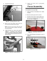
2.
shown in
Figure 1
Figure 1 .
Fence assembly
3.
Secure the fence pieces with lock knob.
4.
Insert the hexason bar to socket, tighten two
set screws on socket to secure the hexagon
bar.
Insert the Hold Down and Guide.
As
Assembly Vertical Bar IV
1.
shown in
Figure 1
As
1.
Figure 1
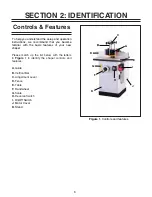
Summary of Contents for G1026
Page 1: ...2 HP SPINDLE MOULDER INSTRUCTION MANUAL ...
Page 2: ... 1 ...
Page 4: ... SECTION 1 SAFETY 3 ...
Page 5: ... 4 ...
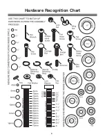
Page 9: ...Hardware Recognition Chart 8 ...
Page 22: ...21 ...
Page 23: ...22 ...
Page 24: ...23 ...
Page 25: ...24 ...
Page 26: ...25 ...
Page 27: ...26 ...
Page 28: ...27 ...
Page 29: ...28 ...


