


15
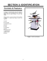
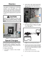
Figure 12.
Forward/reverse switch.
Rotation
Your shaper is equipped with a FORWARD/
REVERSE switch.
See Figure 12.
In many
instances, it will be necessary to flip the cutter
over and reverse cutter rotation. Whenever pos-
sible, mount the cutter so the board is milled on
the bottom side (the side away from the opera-
tor). This does a better job and it is safer for the
operator.
Always check the direction of cutter rota-
tion before any shaping operation. Cutters
rotating backwards will cause unsafe condi-
tions.
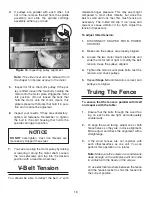
Speed Changes
This spindle moulder is equipped with a special
high speed V-belt. It is designed to withstand the
vibration and sudden shock loads associated with
the operation of a shaper.
To change spindle speeds:
1.
DISCONNECT SHAPER FROM POWER
SOURCE!
2.
Loosen the two motor mount bolts and slide
the motor toward the spindle assembly by tu-
DO NOT take the bolts out.
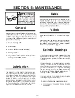
3.
Move the V-belt to a sheave on the motor
and spindle pulleys to select the desired
speed (
See Figure 14
.)
Figure 14.
Speed change belt positions.
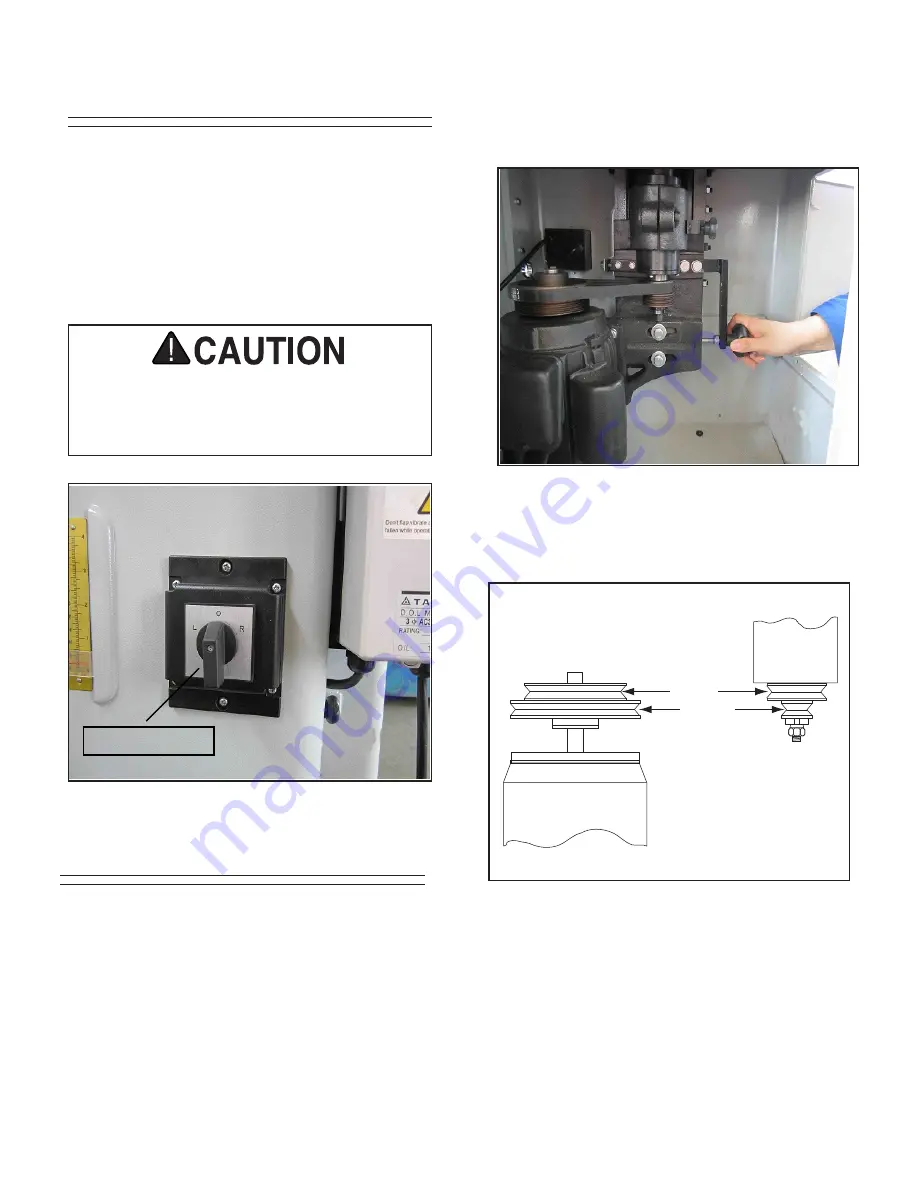
4.
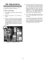
Slide the motor back into position and tighten
the belt. When the belt is properly tensioned,
there should be approximately
tion in the center of the belt when you press
it with your thumb.
5.
Tighten the motor mount bolts.
6.
Spin the pulley to ensure proper tracking.
6mm of deflec-
rning the knob.
See Figure 13.
Figure 13.
7,000
10,000
Reverse Switch
Adjusting the V-belt tention
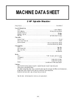
Summary of Contents for G1026
Page 1: ...2 HP SPINDLE MOULDER INSTRUCTION MANUAL ...
Page 2: ... 1 ...
Page 4: ... SECTION 1 SAFETY 3 ...
Page 5: ... 4 ...
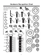
Page 9: ...Hardware Recognition Chart 8 ...
Page 22: ...21 ...
Page 23: ...22 ...
Page 24: ...23 ...
Page 25: ...24 ...
Page 26: ...25 ...
Page 27: ...26 ...
Page 28: ...27 ...
Page 29: ...28 ...


